| Build History - Phase 1 (Complete) | ||
|
Front Frame, Engine, Suspension and Brakes Remove old frame and paint bulkhead Install new frame and engine Fit front suspension and brakes Install Alternator
Rear Frame, Engine, Suspension and Brakes Remove rear floor section Install rear reinforcement frame Install modified frame and engine Fit rear suspension and brakes Install rear firewall
Front\Rear Clutch and Gearbox Linkages Modify Vauxhall Gear Linkage to be correct length Install at correct height for end of shaft to be parallel with gearbox pivot point Install clutch slave cylinders Remote rear gearbox engage pin
Clutch and Brake Master Cylinder Pedal Box Assembly Create pedal box assembly Install in car and attach to mini pedal setup Install clutch and brake lines
Electrical System (excluding engine management) Create \ Install new Fuse\Relay Panel Create \ Install new loom Install car battery Traction Control (only when running both engines) Front \ Rear Wideband Comtrollers
Front and Rear Engine Cooling\Heater Installation Run water piping from front to rear of car Install front engine expansion tanks Install front\rear radiators with fan Install radiator fan cowling Install Air Ducting to Rear Valance Panel Install rear engine expansion tank Create\install new heater core
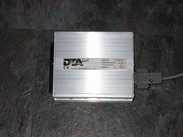
Front Engine QED Throttle Bodies and DTA Management Install QED Throttle Bodies Install adjustable fuel pressure regulator Install fuel pump and fuel lines Install DTA ECU and associated wiring
Create dashboard inner framework Create outer panels \ switch panels Install dashboard components
Install handbrake cable calipers Route handbrake cables from handbrake lever to calipers
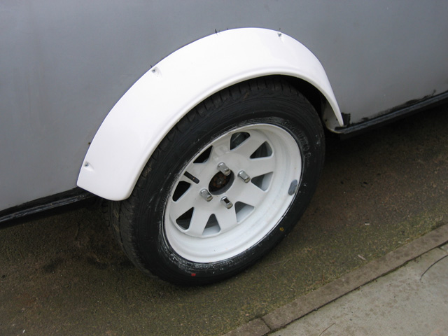
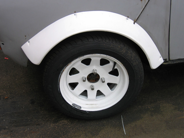
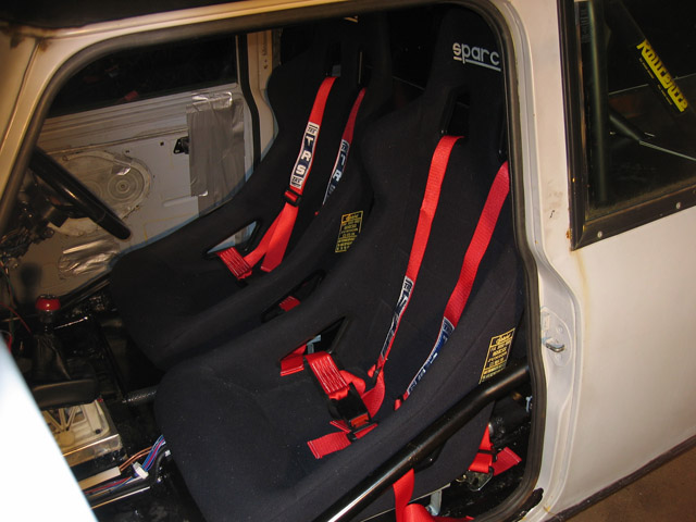
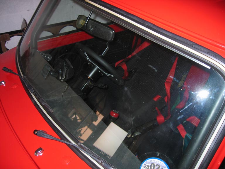
Cosmetic Changes to Interior\Exterior Install extended wheel arches Install racing seats Install racing harnesses
General Engine\Gearbox Upgrades Install Uprated Rods Install Pocketed Pistons Install Uprated Main\Big End Bearings Install Uprated Oil Pump 2.5" Stainless Exhaust Systems Quaife ATB for front gearbox
Rear Engine QED Throttle Bodies and DTA Management Installation Install QED Throttle Bodies Install Adjustable Fuel Pressure Regulator Install fuel pump and lines Install DTA ECU and wiring
Install Nitrous Bottle Install Rear Nitrous\Fuel Pulsoids Install Distribution Block and Crossfire Injectors Install Throttle Activation Switch Nitrous Bottle Heater and Pressure Gauge
General Bits'n'Bobs that don't fit into any particular category Washer Bottle Installation Wiring \ Pipe Tidying Cut Slick Tyres Uprated Springs Stronger Engine Mounts Fire Extinguisher Heated front windscreen Extra rear speakers
|
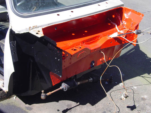
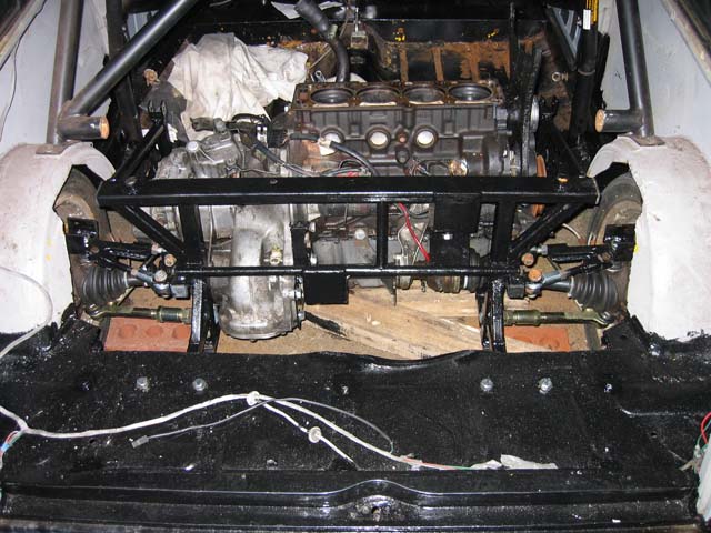
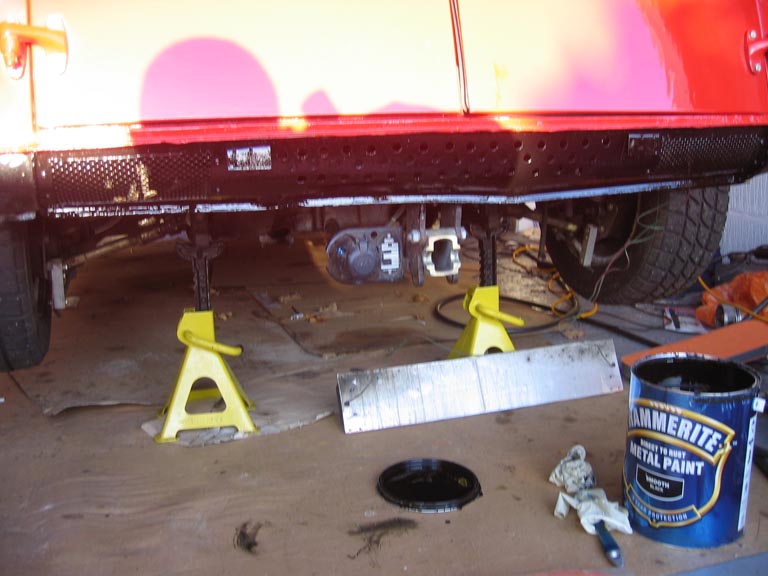
I came across a mini estate for sale which already had one AMT 16V frame fitted to the front which removed a lot of the front end work effort and also saved me having to order another AMT frame as the original one I was planning to use was already on order. The existing frame was quite old and would require a strip down and repaint before use. (Click on pictures to see larger version) Front Frame, Engine, Suspension and Brakes Installation I removed the old AMT frame and all ancillaries on the bulkhead then painted with copious amounts of hammerite to try and fend off the rust demon. :)
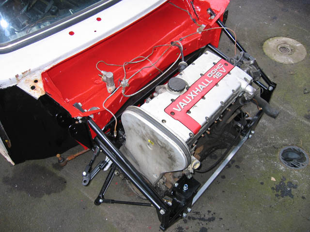
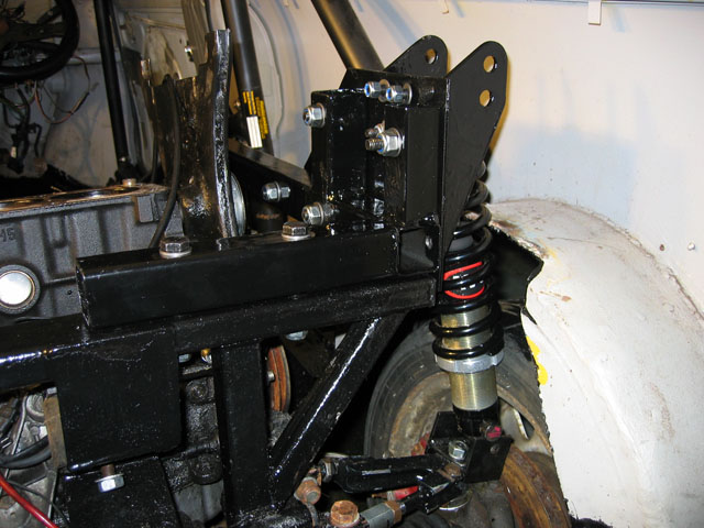
This is the new AMT frame mounted and the first engine dropped into place. Also same install with front end placed on which shows just how tight the final result will be.
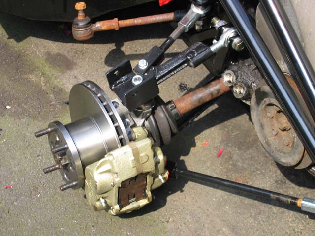
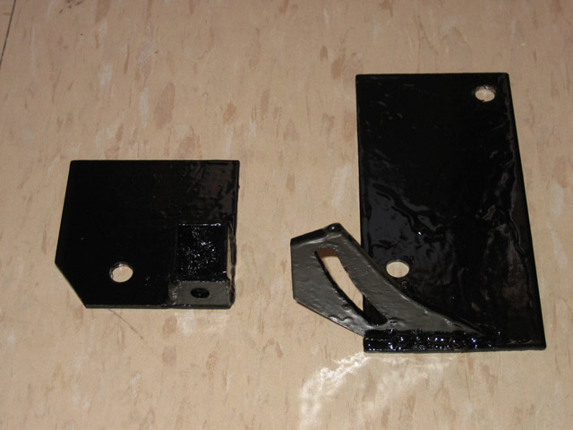
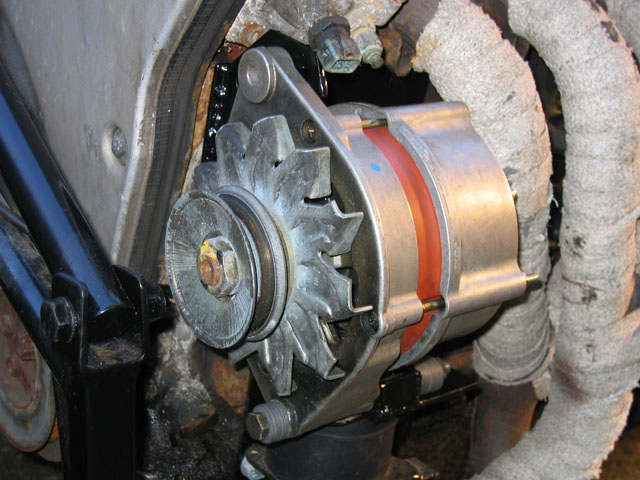
The front metro turbo brakes are also now in place. Found that the AVO Coilover Shocks didn't have a large enough hole for the mount bolts to fit so had to drill them out and the kit didn't come with any spacers to remove the play in the upper and lower mounts so some spacers were made out of nylon bar. The upper arm has been adjusted to 6.75" with the upper tie bar set to make this arm 90 degrees to the frame. (The lower arm and tie bar will be setup at a later date) I may change the calipers to some alloy ones at a later date to save some weight as the cast ones are really heavy. There isn't enough space to install the alternator in the standard Vauxhall location at the rear of the engine so new brackets had to be made to place the alternator at the front.
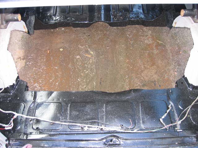
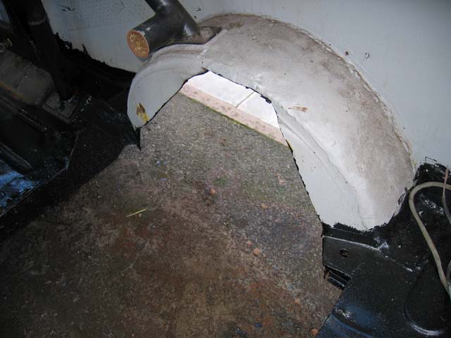
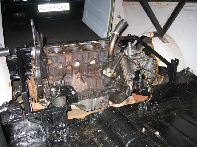
Rear Frame, Engine, Suspension and Brakes Installation This is where the real work began as a lot of the basic front work was already completed. Firstly a large section of the rear floor was removed to enable space to install the modified AMT frame and engine with the wheels still centered within the arches. After much measuring of the front frame, mounts and suspension it lined up well with the AMT frame front alloy crossmember mount points sitting just ahead of the rear bulkhead. A large portion of the rear bulkhead had to be removed so extra strengthening is to be added on the floor later. A section of the rear arches was also removed to allow space for the suspension arms and the coil over shocks.
The rear floor would now be the bolting point of the mounts which usually fix just below the front bulkhead at the front of the floor pans on the driver and passenger side. The rear floor was way too flimsy to be able to withstand any load of this type so a subframe was constructed to fit below the remaining rear floor.
The back mounts on the AMT frame, which bolt to the footwells, were too low to attach to the rear floor so they were removed and raised approx 4 inches to connect just above the lower arm mount point. The engine was installed into the frame before fitting to the car as it would be hard to install when the frame was in place. The front alloy crossmember mounts are connected to the rear firewall with some reinforcement to stop the floor tearing. With the rear floor subframe installed you can jump on the rear floor and no flex is visible.
The top mounts are bolted to the main cross member of the AMT frame and also at the front of the frame where the extra brace bars are normally installed. The sides of this assembly are then attached to the remaining cross member portion of the rollcage. By utilizing 3 different mount locations on the rear frame to spread the torsional stresses i'm hoping it will be strong enough to take the load without too much shell flex at any one point. This frame section also holds the mount points for the rear coilovers, by using this as the rear suspension mount it will hopefully relieve the body of the extra stress of the rear suspension load.
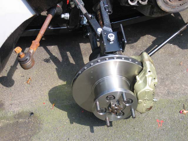
Again the upper arms were set to 6.75" and the tie bar set to make the upper arm 90 degrees to the frame. The wheels sit quite centered in the wheel arches already, this position should be somewhat adjustable as no steering is required on the rear so the upper\lower arms should be ok to adjust to make the wheels sit more forward\backward as required (I have moved the spacers on the upper arm so that they are both to the rear of the mount point, this has moved the upper arm approx 5mm forwards without then affecting the angle of the arm to the frame by adjusting the tie bar). The brakes are currently identical to the front setup (metro turbo setup) but I will need to either add an extra pair of calipers for the handbrake or install some alloy 2 pot calipers with handbrake cable function to make passing the MOT a little easier as the parking brake needs to be independent of the main braking system hydraulics.
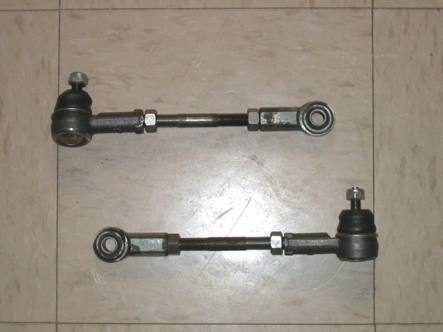
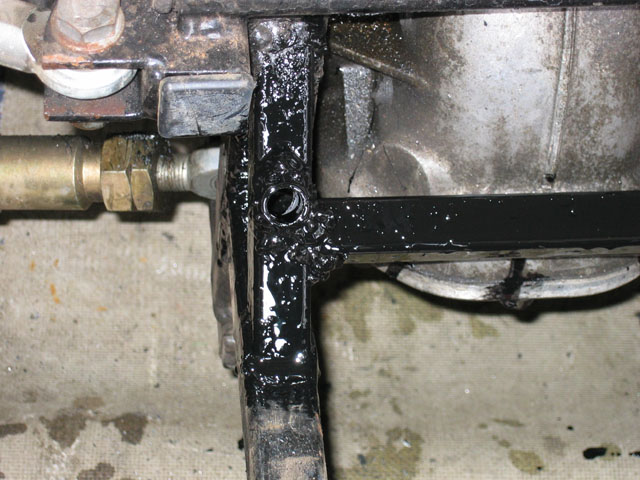
As it was basically a front setup at the rear it would need locked off steering arms, these would provide the rear toe adjustment but had to be located so as to minimize any bump steer effect. After testing many mount points this mount point was chosen as it doesn't show any bump steer through min-max suspension travel. I've now added a cross beam and sleeved the mount points to add quite a lot of strength and eliminate any flexing issues.
Required for the MOT and also my own peace of mind was to separate the rear engine from the front cabin. I was originally planning on an aluminum cover to seal the rear engine out of sight but this was removed as it was just too difficult to seal properly, didn't offer much in the way of noise reduction and also people were complaining they couldn't see the rear engine at shows etc. In light of this I have opted to construct a firewall between the rear engine and the front cabin area. It has been constructed from 3/4" MDF and 5mm Polycarbonate.
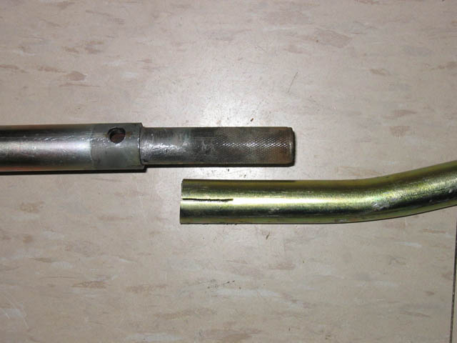
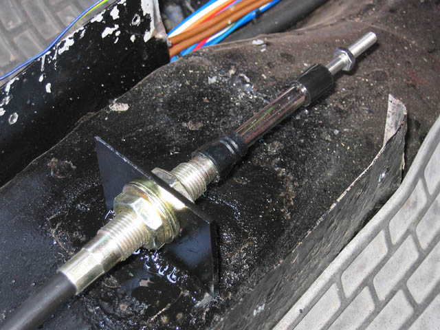
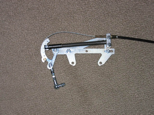
Front\Rear Clutch and Gearbox Linkages The standard Vauxhall gear linkage is way too long for the mini so had to be shortened about a foot. I decided that rather than have the main adjustment right on the pivot point, which is hard to get to, I'd make it adjustable nearer the gearstick itself. The gearstick assembly needs to be installed at the correct height so the shaft runs parallel to the floor as per the standard Vauxhall installation..
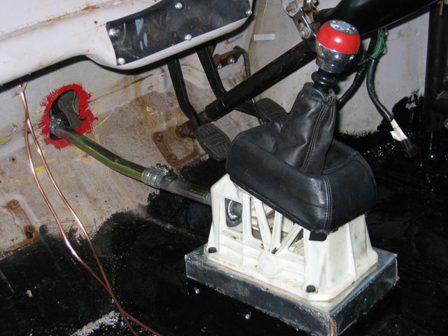
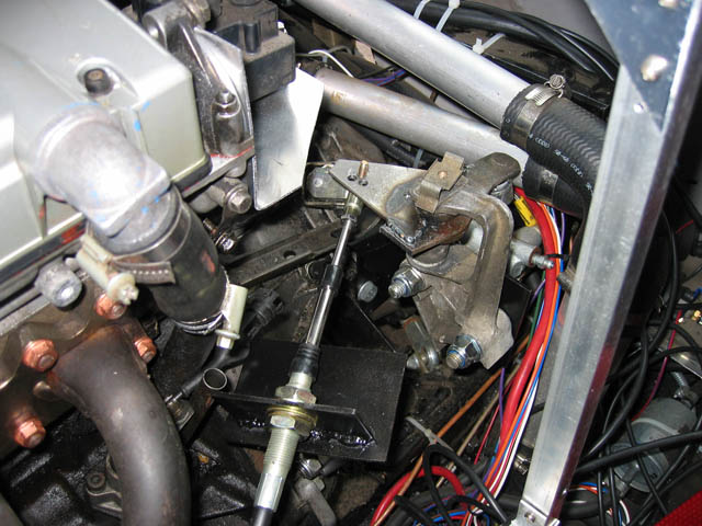
Finally got round to installing the gear linkage in the car, had to cut down the pivot bar that fits on the rear engine mount and also needed to knock a big dent in the bulkhead so the pivot bar would move enough to get 1st and reverse gears. Surprisingly the gear setup worked at the first attempt with all gears available and no messing to get 5th and reverse both to work at the same time. The gearstick is mounted approx 2-3 inches above the transmission tunnel on an aluminium box section to ensure the linkage bar was parallel to the floor.
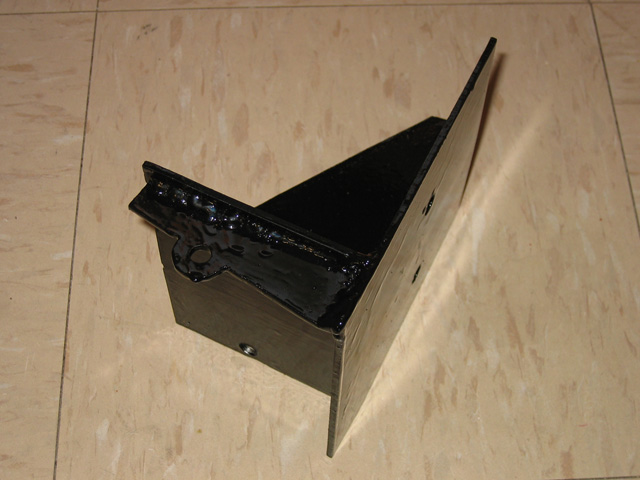
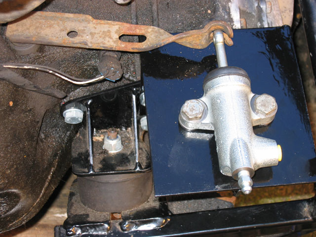
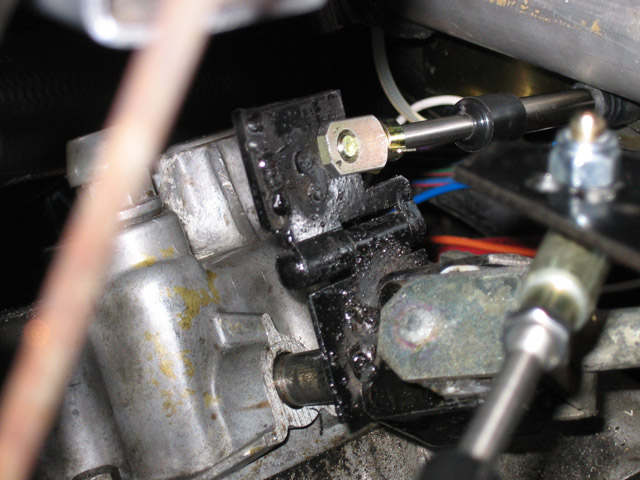
While a cable clutch would be the simplest to install for the front engine it wouldn't be so easy to get a cable to reach the rear engine so I decided on hydraulic instead. Upon measuring a standard Vauxhall install I found that approx 30mm of travel is required to operate the clutch lever on the F20 gearbox. The old style horizontally mounted mini slave cylinders have a max travel of approx 40mm so would be suitable to use to push the clutch lever rather than pull with a cable. A suitable mounting place was not available for a simple bolt on so one had to be constructed to suit which bolts to the engine mount point and the side of the gearbox.
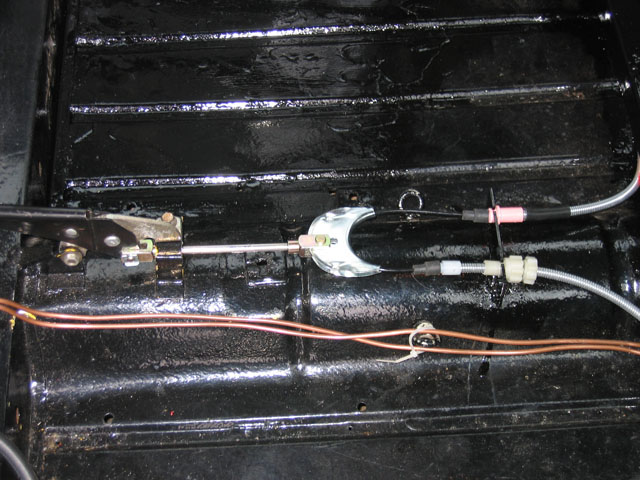
The rear gearbox linkage would be much more difficult and I decided rather than use a solid bar assembly (which would be quite a mess in the car) I would use a cable setup. The cables are a special push\pull type which are capable of handling approx 70kg of forward\backward force (these same cable types are used in several high performance kit cars so should be ok).
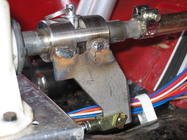
Connecting these cables from the front gear linkage would be quite difficult though as it rotated as well as moved back\forth. I also wanted to be able to disconnect the rear link so the front engine was available for general traveling around to save on fuel costs. The first cable to install was the forward\backward motion cable, this is the one which needed to have the simple disconnect option. I decided the best way to achieve this was to make a sleeve which fitted over the front gear linkage which would push the cable forward\backward but be able to swivel on the shaft so the left\right movement didn't affect the cable position. I used a removable pin in the assembly to achieve the required simple disconnect option.
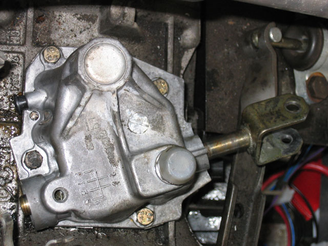
The gear selector on the F20 gearbox has been modified to face the other way as getting the cable all the way around would have been problematic.
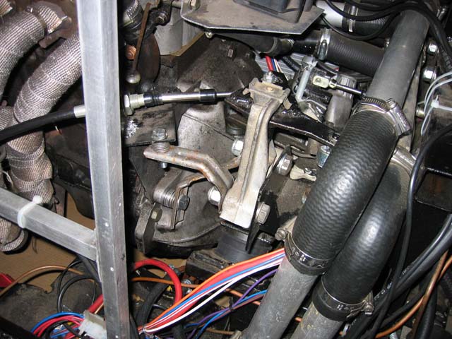
I modified the rear engine mount which contained the gearbox linkage pivot bar so it could be installed on the other side of the gearbox with a custom bracket which linked with the clutch cylinder bracket and then chopped the pivot bar so it was at approx 90 degrees rather than straight in order to get the cable to connect and push\pull from the side rather than direct from in front. This is now working correctly and I can get 3rd\Neutral\4th in unison with the front gearbox. The bracket holding the cable in place is bolted to the gearbox housing so should be quite secure.
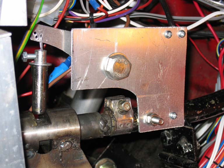
The cable required for left\right twist motion would be a little more difficult to install as I didn't want to lose too much footwell space on the passenger side (I initially wanted to install this cable connected to the gearbox link directly but found insufficient room to fit it in. Eventually I found this location a good compromise and only lost a few inches of footwell space.
The left\right twist connection on the rear engine itself would also prove difficult, with so many wires, water pipes and fuel pipes there was very little room remaining. Once installed I also had problems getting 5th and rev on the front engine, I think this was due to increased load on the gearstick shaft causing some flex somewhere. I good attack of the Vauxhall gearstick cage allowed just enough extra left\right movement and now all gears are available.
I've noticed that the rear linkage brackets were able to flex sometimes if the gear wanted to be a little difficult resulting in the front engine gear being engaged but the rear gear remaining not completely engaged but you wouldn't be able to feel this from the gearstick which resulted in many messed up 1/4 mile attempts. To counter this I have added a couple of extra brackets onto the mounts and this has removed all visible flex and the shift feels much more solid and if a gear doesn't want to go in you can feel this now in the gearstick.
Since completing most of the dashboard it's become difficult to reach the engage pin to engage\disengage the rear gearbox linkage. To work around this I have mad a remote control for the pin to be removed\installed using one of the mini choke control cables to lever the pin in and out of the linkage assembly.
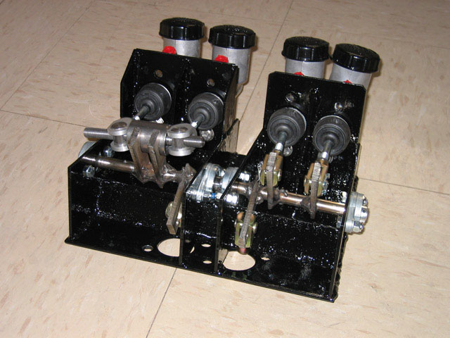
Clutch and Brake Master Cylinder Pedal Box Assembly As I was using 4 pot calipers front and rear along with 2 clutch slave cylinders there wasn't really any option but to make my own master cylinder pedal box assembly. This has been the hardest part to make so far but i'm pleased with the result (if it works of course when I get the car on the road) :o) There are 2x 0.625" master cylinders for the front and rear brakes and a balance bar assembly to provide brake split adjustment front\rear. I also have 3 mount points on the input bar so can adjust the pedal ratio to increase or decrease required pedal travel \ pressure. For the clutches I have used 2x 0.75" master cylinders as the stock mini master cylinder was 0.75". Each clutch can be adjusted separately on the master cylinders and again I have made allowances to be able to adjust the pedal ratio to increase\decrease maximum clutch travel. The pipework for the brakes and clutches was a nightmare :)
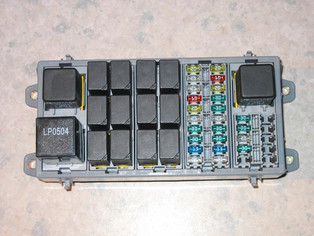
Electrical System (excluding engine management) The existing electrical system in the mini was a complete mess so I decided to install a new modernized electrical setup rather than try and plumb into the existing relays, fuses and wiring. The job ended up being much more complex than I had originally thought, over 30 hours was spent just designing and documenting the electrical system to replace the entire mini setup apart from the wiper \ indicator stalks, ignition switch and physical lights. Instead of small pockets of fuses \ relays I purchased a modular fuse \ relay panel which could be built up in parts to suit the application. Most main power requirements are now relay fed rather than just through the switches and stalks. This is a picture of the relay \ fuse assembly before any wiring was completed, it looks much better than the standard mini setup and will hopefully be more reliable and easier to trace faults if they arise.
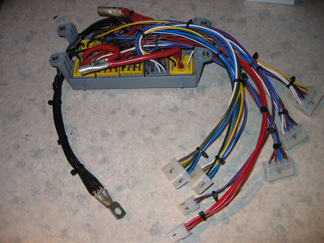
This is a picture after the wiring nightmare had been completed on the back of the assembly. I've changed my mind about making it easier to find faults :)
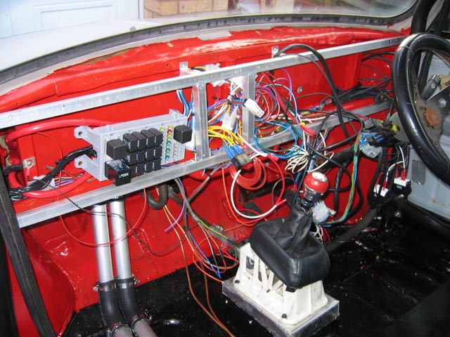
I was quite surprised to find that all the lights, indicators and wipers worked first time as expected without any need for changing the wiring plans at all. I guess all the time spent on the design was worth it after all :) Looks quite a mess in the car currently but it will all be tidied and hidden behind the dashboard panels at a later date. Only the engine connections left to complete now.
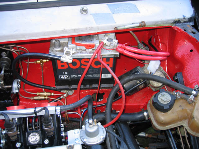
Thanks to the changes on the front bulkhead I am able to install the battery in a handy location.
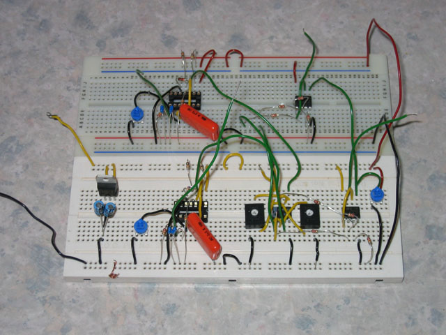
After the terrible wheelspin problems at the Mini Showdown I decided to start work on the traction control unit earlier than planned rather than go for slick type tyres or an LSD. The control unit will work based on the RPM signals from both engines This is a picture of the early prototype which has yet to be tested.
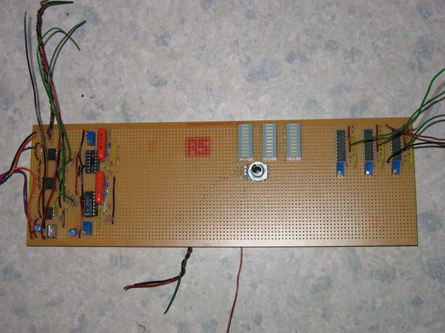
The prototype looks to be working as expected and i've expanded slightly on the design by adding 3 led bar graphs which will show the amount of slip on the front\rear and the threshold limit set. This is a picture of the final circuits installed on stripboard but still needing to complete the link wires from the bar graph LED's and the stripboard itself needing to be trimmed into 3 separate parts. I'm hoping to have this completed in time for Ten Of The Best 2006 which is possible assuming it works first time out when installed in the car :o)
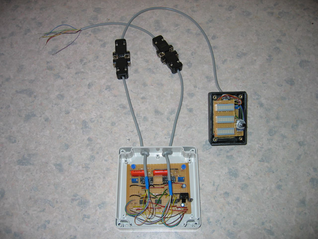
Once all connected up properly and cabled in the unit looks quite qood.
Still have the front face plate to finish for the LED display part but other than that it is all completed. I have briefly tested it in the car but only in neutral and by setting really silly settings in the DTA which wouldn't be used on the road. The result looks promising as it successfully cuts the ignition on the front engine if the front rpm exceeds the threshold set compared to the rear and the rear works the same also cutting if the rpm at the rear exceeds the front. Quite by accident I've also found it to have a secondary function as a flamer kit. The first field test will be TOTB 2006 on Sunday now so here's hoping it all works as well as I hope to get my 1/4 mile times down a bit lower :o) After testing it has been found that a complete cut of the ignition is too much and causes the car to bog down very badly. Now instead of using the shift cut on the DTA i'm utilizing the launch control input which uses ignition retard as the primary power control and only resorts to ignition cut if this fails to control the wheelspin. I only had a chance to test this briefly before the car was put away for the winter but the initial test was very promising allowing a controlled launch even in 1st gear :o) As you can see below the face plate has also been completed.
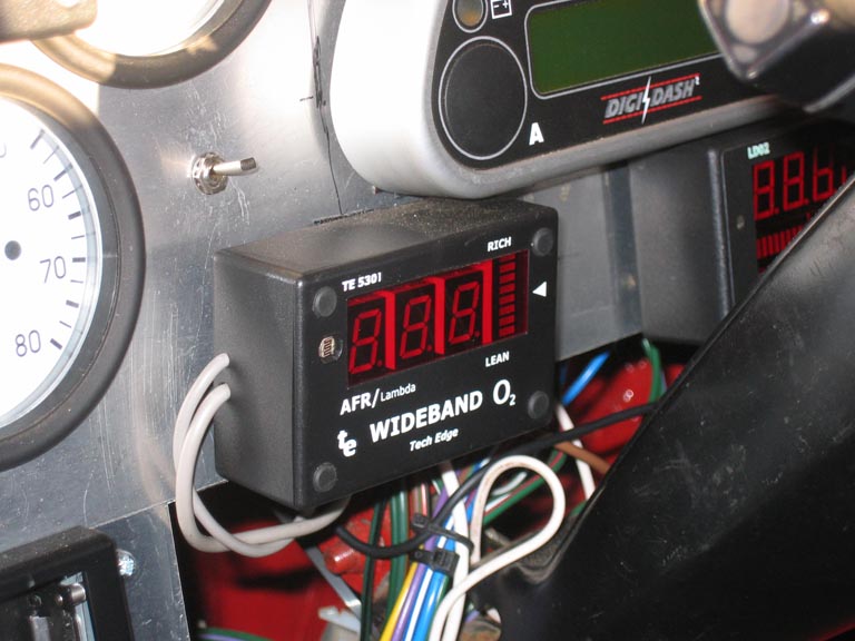
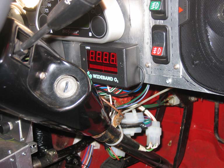
In order to monitor the a\f ratio accurately I have installed front and rear wideband units, this provides useful information during mapping and also monitoring capability when adding the nitrous to the engines. The front unit is an early WBO1.5 unit from Techedge, the rear unit is one of the much newer WBO2 DIY units from Techedge which is capable of logging for up to 20 minutes and has inputs for 3 exhaust temp probes, 3 general 5v inputs and RPM input. Both units have outputs capable of connecting to the E48 ECU's to enable closed loop control for lean cruise etc.
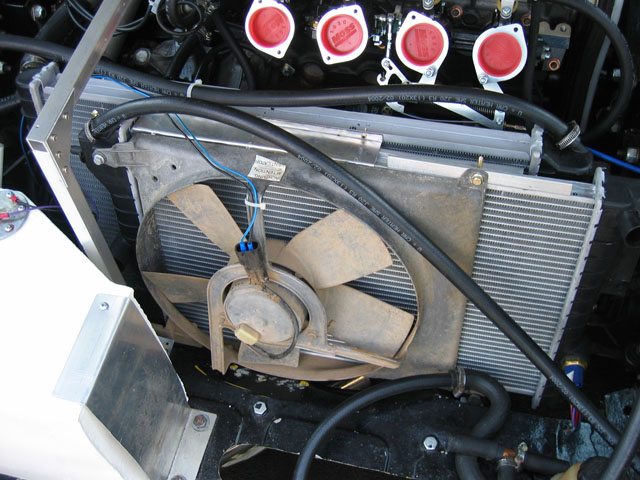
Front and Rear Engine Cooling\Heater Installation Although initially I installed both radiators in the rear of the car for front space purposes it's proved to be insufficient to cool both engines when running for longer periods of time due to the same air flowing through the rear engine radiator after it has already flowed through the front engine radiator. Due to this I have redesigned the radiator setup with a front mounted radiator and a rear mounted radiator. In the front there is now a 2000 Renault Clio 1.9DCi radiator with a 7" fan pulling air through the radiator and another 7" fan pushing air through a different area of the radiator (this had to be done as there simply wasn't space for a single large fan mounted on one side of the radiator. Although this radiator is slightly smaller in overall frontal area compared to the normal Vauxhall one it has the fine meshed fin arrangement so should cool sufficiently due to the large surface area of the cooling fins. In removing the front to rear piping (along with the extra water in these pipes) I roughly estimate that i've saved around 10kg's in ballast which should prove to be a bonus.
The rear engine now has the cooling fan to itself and I have redone it to use the larger radiator that was used for the front engine which was a South African Cavalier Turbo type and this has cooled the front without problems.
In order to remove the hot air from the rear engine compartment I have made a fan cover that directs the air out under the rear floor. I'm also hoping that there will be some vacuum effect under the rear of the car so air will be drawn through the radiators when cruising rather than the fan kicking in every 10mins or so.
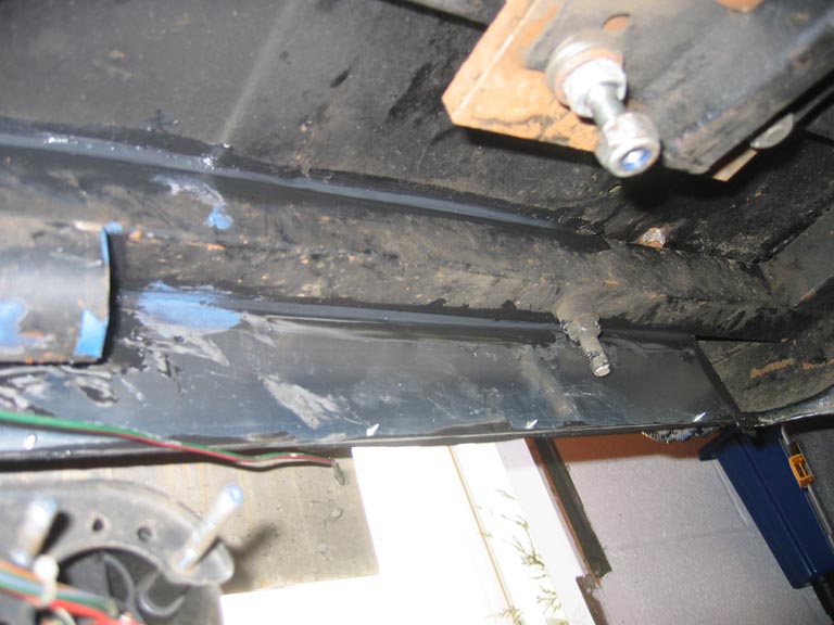
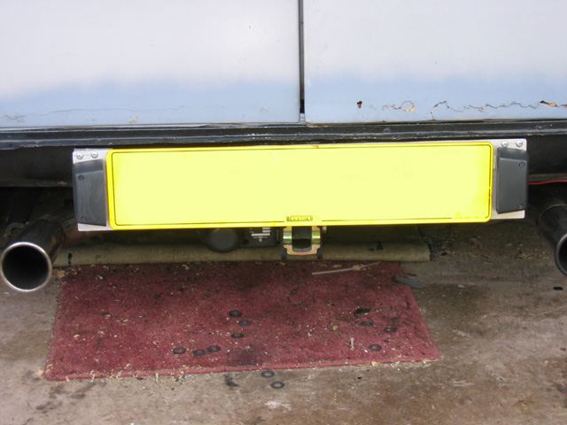
There appears to be too much air turbulence under the boot floor to allow clean air flow from the radiator under the car so I have made the rear valance a type of air duct in the hope that there will be a partial vacuum at the rear of the car to draw the air through the radiators. This involved basically cutting away some of the rear valance and also drilling it behind the numberplate then boxing it in using aluminum panels under the car to direct the air from under the boot floor.
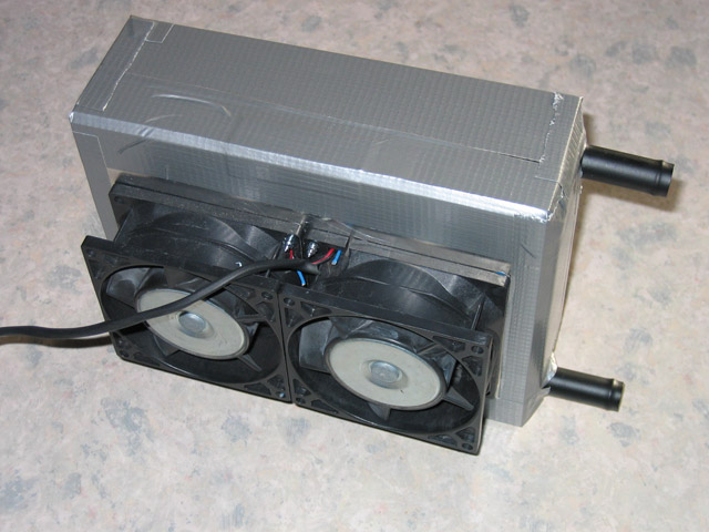
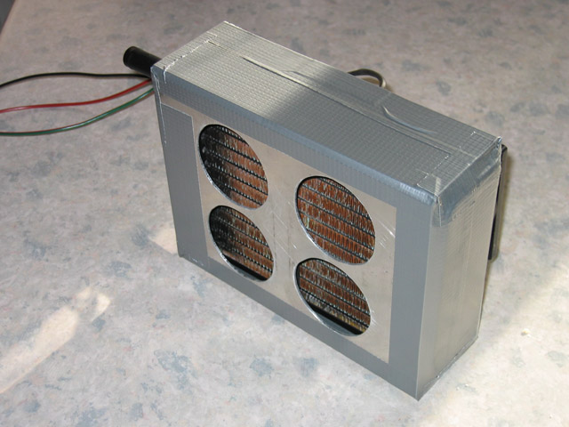
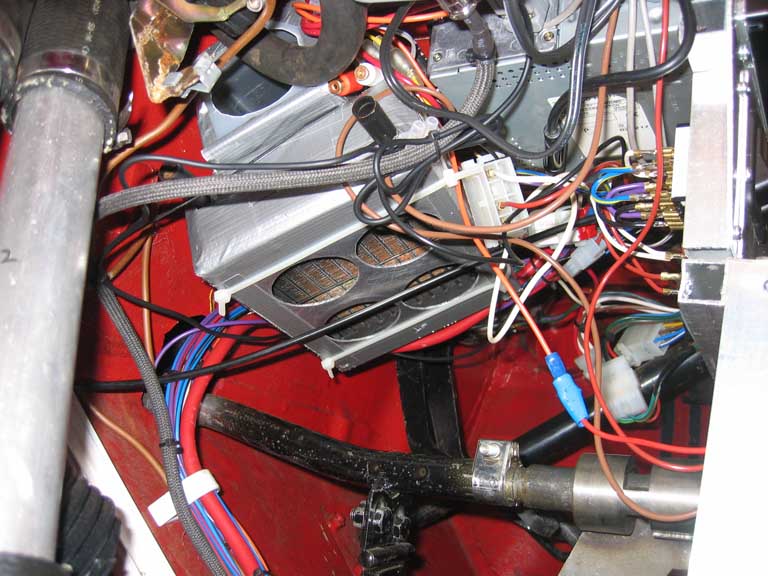
As I want this car to be fully road going rather than just a straight racer I still needed a heater. In order to save weight I decided to make a new lighter heater than the standard mini one (which is pretty useless anyway). I used a standard mini heater core, encased it in aluminum and used 2 high speed heavy duty PC fans to supply the required air flow through the system. The new unit weighs less than 1kg (without water) compared to approx 5kg for the stock mini item, the fans will have 2 speeds available and on initial testing seem to flow at least as much air as the stock mini setup. The windscreen is due to be replaced by a heated version so there will be no need for demist vents. The intake air will be supplied from the the front of the car to avoid general condensation problems in wet \ damp conditions. A late model mini heater valve will be installed in the heater water pipes to provide the control of the heater temperature. This is the basic lightweight heater core before installation into the car.
This is the new resting place of the heater core, quite a tight fit so I will simply leave the vents to add hot air in the foot wells rather than try and plumb in extra vents which really would be more cosmetic than actually needed. As you can see i'm using the later type mini heater water valve, when using this setup there also needs to be a bypass pipe so that the water can still flow through when the water flow to the core itself is shut off.
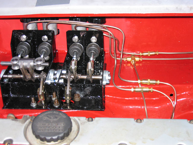
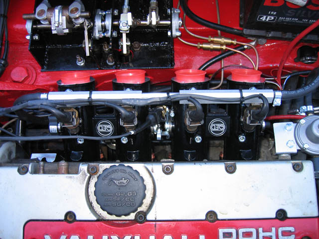
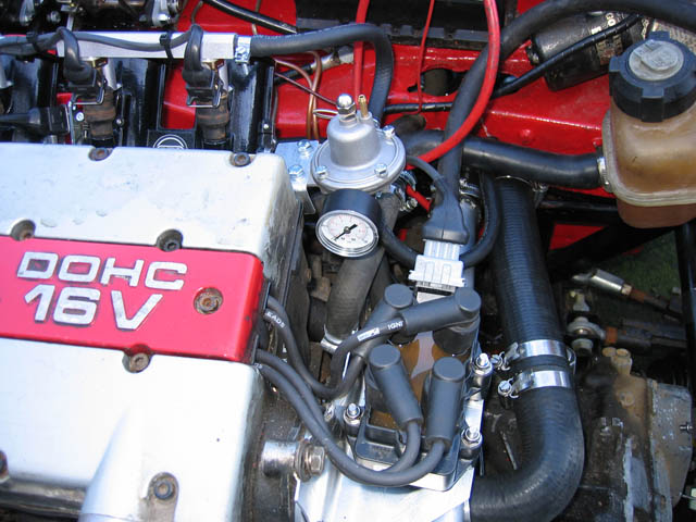
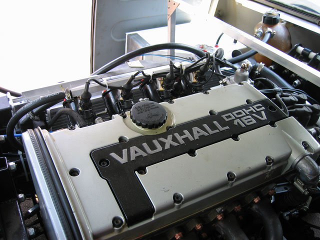
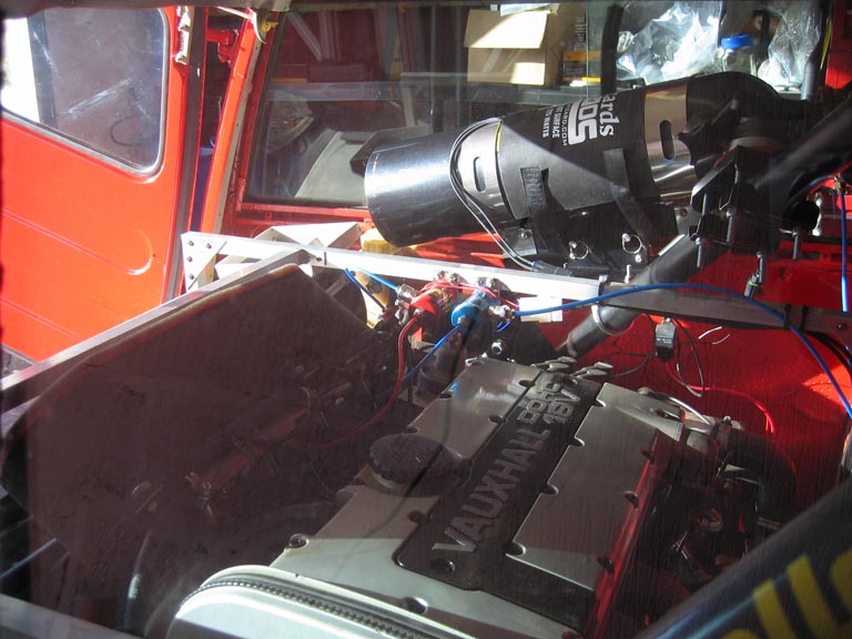
Front Engine QED Throttle Bodies and DTA Management This is the QED Direct to head throttle bodies installed on the car along with the fuel rail, injectors, coil pack, adjustable fuel pressure regulator and hoses. There won't be much detail in this section as it deals with the bolt on aspect of the setup rather than the tuning which has it's own section on the website.
Here is the Jenvey throttle linkage and the DTA E48 ECU before fitting to the car as you won't be able to see the linkage or the ECU very well once fitted. I was originally going to design my own throttle linkage but as I will need two identical setups for front and rear I opted to purchase a ready built solution.
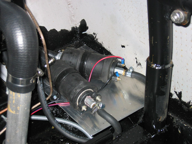
Managed to find a spot for the front and rear fuel pumps that is fairly out of the way. The pumps are the same as the ones used in the Jaguar XKR so should be able to provide ample fuel for my requirements.
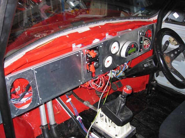
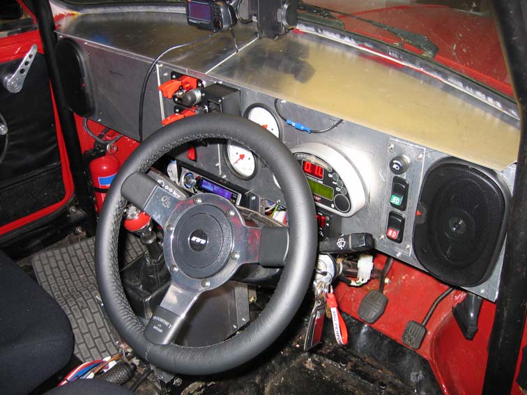
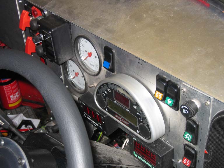
Rather than lots of dials I have opted for the digital dashboard solution for the primary items required by the MOT (Speedometer, Warning Lamps, Odometer etc). I have installed separate RPM gauges for each engine though as the dashboard would not be able to provide information about both engines simultaneously. The dashboard instruments are comprised of an ETB Digidash 2 Lite and 2x 80mm ETB RPM Gauges.
Here are a couple of pics of the initial install of the dashboard in order to complete the MOT. Still a lot of work to go though including the centre section by the gearstick for the heater controls\radio, install the speakers, make a top cover and flock the whole assembly so it looks a bit too stripped out racer in bare aluminum.
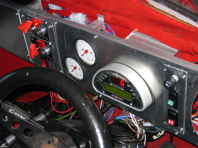
I have now moved the dashboard a little further from the bulkhead to add a little sound proofing and also to allow more space for wiring etc. Also I have now completed the gearstick surround and the radio\heater control panel so almost looks like a proper dashboard now with only the top cover to complete and then i'll be able to decide on flocking the dashboard or carbon fibre effect. Only time will tell if I can actually hear the radio over the engine noise :o)
And finally a dashboard with a top so it's looking much more normal now, still need to decide on carbon fibre or flock but that will probably be next year now.
I've finally decided on a cover plan for completion over next winter for the dashboard, will cover the main plates of the dash with black flock and the smaller panels with switches etc will be re made from thin carbon fibre sheet. I've also fitted a new steering wheel as the old was was a bit on the rough side.
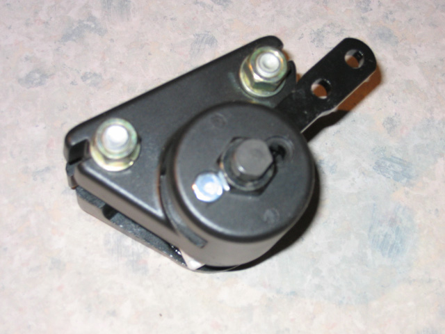
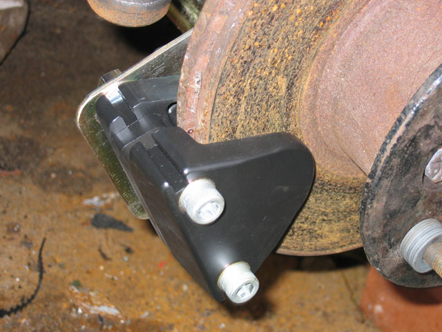
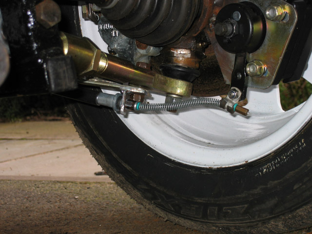
As the handbrake needs to operate independently of the main hydraulics for the MOT I have decided to install an extra set of cable operated calipers at the rear rather than changing the main 4 pot calipers for some combination hydraulic\cable calipers. This route was chosen partially due to cost and also due to keeping the braking system simple. The Wilwood mechanical calipers have been attached to the rear of the hubs via some brackets which have been welded into place.
The calipers appear to work well, if you manually move the lever the discs go quite stiff to turn. With more leverage available using the proper handbrake lever they should be just enough to pass the MOT requirements. A handbrake cable from a modern vehicle was used rather than the old mini type cable arrangement for ease of installation.
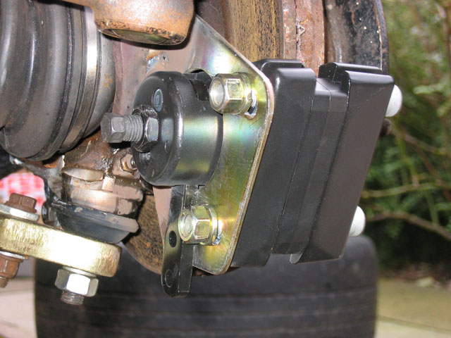
This handbrake setup proved to be very borderline on a MOT test barely passing the minimum requirements, I think that the problem was that there simply wasn't enough lever force being applied to the caliper by the handbrake cable. This is now hopefully resolved as i've extended the lever on the caliper so should have increased lever force on the brake by about 2.5x, this should make the handbrake much more effective.
Cosmetic Changes to Interior\Exterior I really want to minimize the amount of visible changes to the exterior of the car so it retains the original mini look. There were some alterations which could not be avoided however.
In the interior I have a couple of Sparco bucket seats, these may be a little uncomfortable for long journeys so may be changed for some sports recliners at a later time. Rather than use the standard mini seatbelts I have purchased 4 point harnesses.
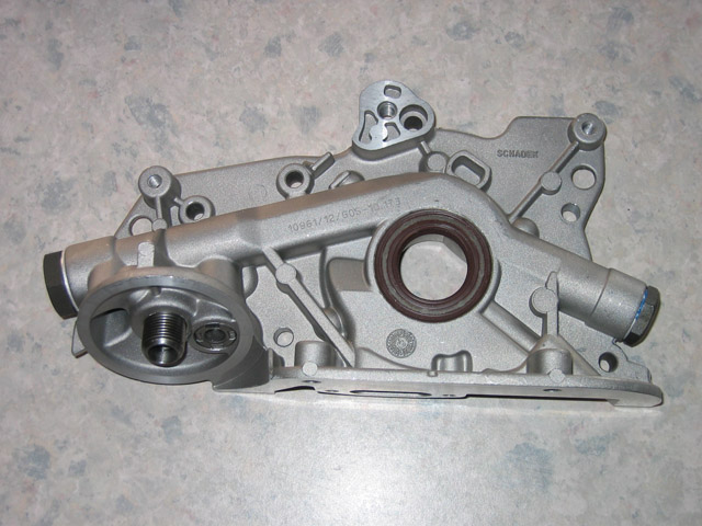
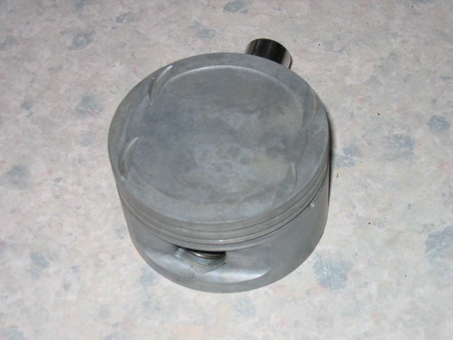
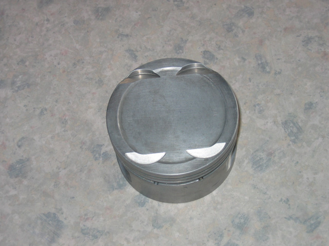
General Engine\Gearbox Upgrades In order to increase the rev limit on the engines (partially required to enable 60mph in 2nd gear but more for future reliability) there are a few main components which need to be changed from the factory standard to more suitable parts. (Of course all the standard XE rebuild components were replaced as part of the job but not detailed here as they were off the shelf GM parts such as water pump, cam belt + idler pulleys, valve stem seals, gasket sets etc). With these components installed the engines should be able to rev safely to approx 8250rpm, any more than this would require more replacement parts and becomes increasingly expensive which was to be avoided where possible. As these engines were of an unknown mileage (but at least 15 years old either way) the oil pump was replaced. Rather than use a standard replacement 20XE pump the one which is installed in the more modern Z20LET was used. This Z20LET pump is capable of better rpm stability as well as increased flow generally, it also utilizes steel internal pump gears where the old XE pump uses plastic ones which are known to break at high rpm. Visually they are virtually identical apart from an extra lug at the top of the pump which needs to be filed a little to clear the cam cover back plate and the centre seal needs to be removed and replaced by one from an XE. (this is included as part of the bottom end gasket set). Also with this pump the oil pickup pipe needs to be created from scratch as the stock XE one does not fit to the Z20LET pump, you cannot buy a direct fit one so you need one from the Z20LET engine and then chop\weld to create one with the same shape as the stock XE one.
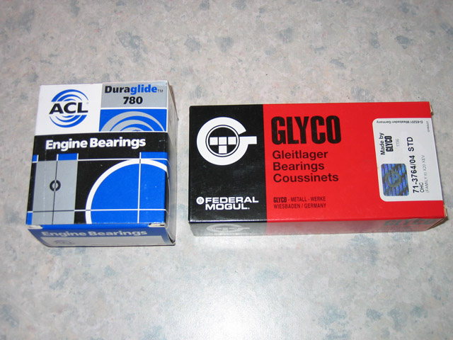
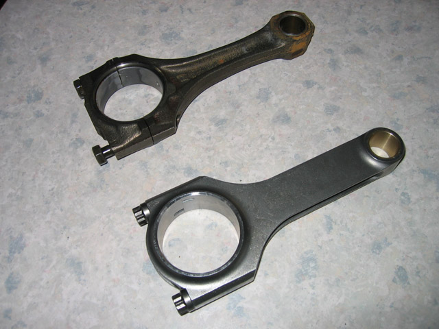
Again more for reliability under a most probable future stressful life I have fitted some main\big end bearings which are of a better compound than the stock items (stock being copper aluminum). The main bearings are a lead copper mix and the big end bearings are the Glyco 40 compound bearings which are a lead iridium mix, these Glyco 40 bearings are also 1mm wider than the current stock GM ones (GM used the wider bearings in very early XE's). One of the weaker items when increasing the rpm limit on the XE are the factory piston conrods\rod bolts. As these were now very old and probably fatigued I opted to purchase some steel H pattern rods which will be safe well above my required rpm limit, these also came with arp 2000 rod bolts. Another bonus is that these each of these rods weigh 110grams less (575grams compared to 685grams) than the factory ones which should help also. As I would like to see approx 210-220bhp normally aspirated before adding any NOS it would require new cams and possible head work, the XE valves are already close to the current piston valve cutouts so while in bits thought it a good idea to have the pistons machined to accommodate an extra 2mm of lift which should enable pretty much any spec of cam to be used. I was originally not going to do this but I found that the pistons were the earlier mahle forged items rather than the later cast ones so a quite substantial amount stronger. The original is on the left and the pocketed on is on the right.
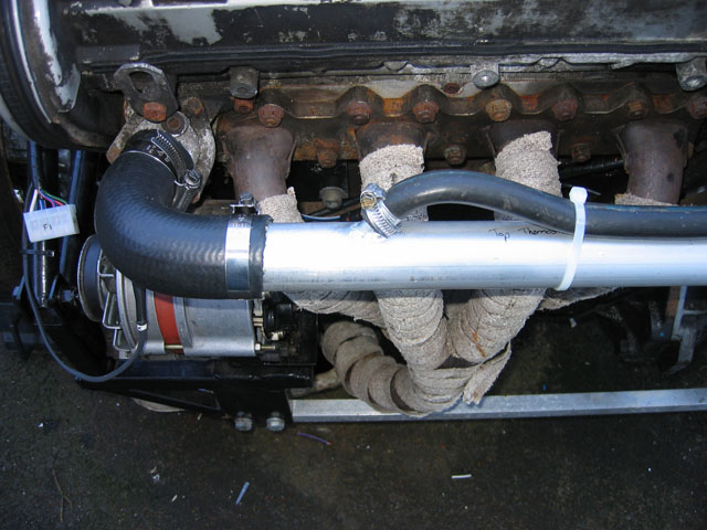
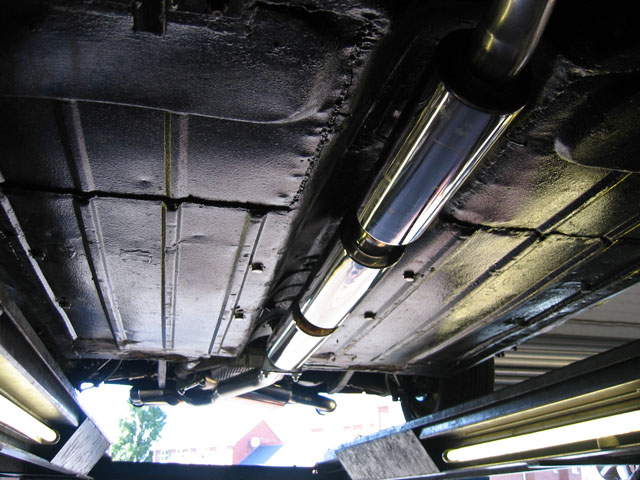
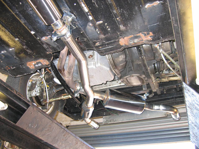
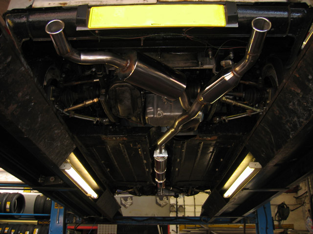
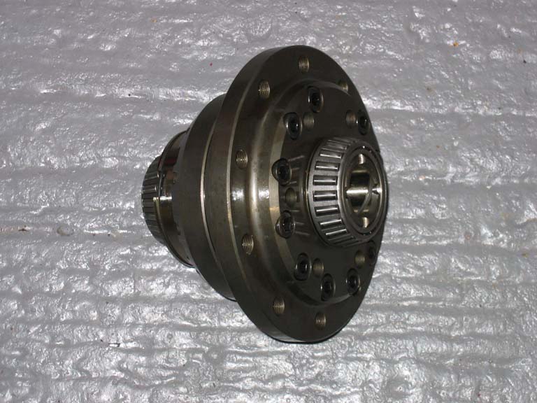
Fitting the exhausts would be interesting so say the least as there's not that much room at the back for 2 systems. I decided that I wouldn't have very large tailpipes as it would look wrong and I also wanted to make the front system as quiet as possible but still maintain the 2.5" bore. This was started off by installing 3 boxes in the transmission tunnel and then only a smaller box at the rear due to space issues. The rear system will be very loud as even though it has quite a large back box the distance from manifold to tailpipe is only about 3 feet. To improve the front end grip when coming out of corners and also for drag racing I have now fitted a Quaife ATB Limited Slip Differential, can't wait to give it a try on the strip now :o)
I may need to install another LSD in the rear eventually but at the current power levels there really isn't any need and also makes the car easier to get around corners with less chance of spinning off as it will only break traction one wheel or the other at the rear making the car safer on the road and track.
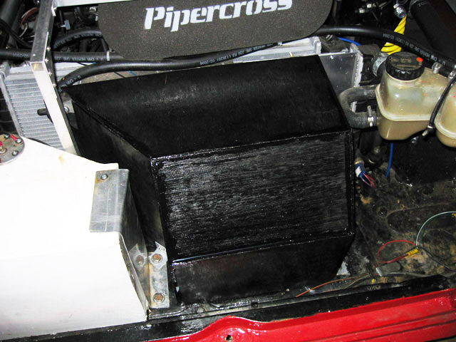
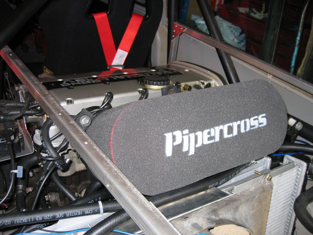
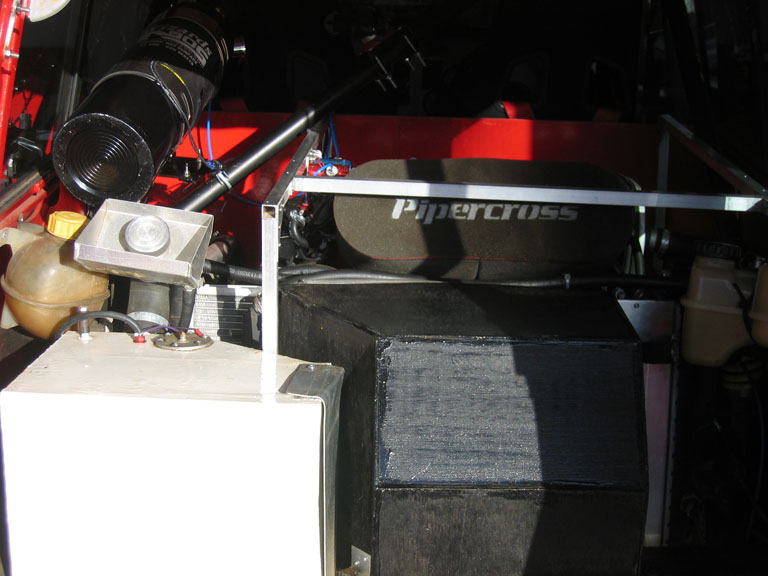
Rear Engine QED Throttle Bodies and DTA Management As the rear setup will be very similar to the front there won't be too much detail here. This is a pic of the rear engine with TB's installed and another with the filter installed ready to roll.
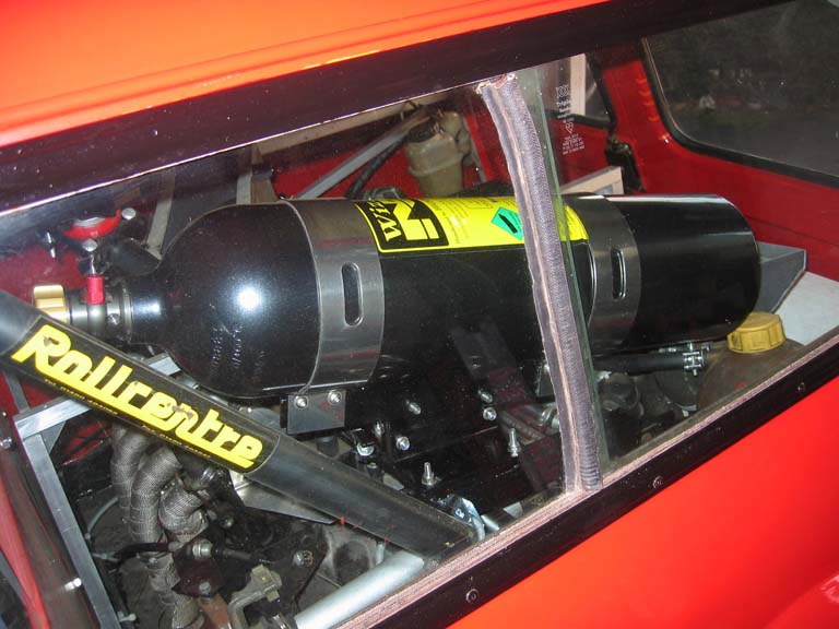
Rather than just add the nitrous install to the end of each engine section I thought it more fitting to have a complete section just dedicated to the nitrous as it will be such a large key element of the mini going forwards. After much reading on the subject I decided to go with the WON setup as this is really the only reliable setup that will control the extra power delivered in a variable fashion, although initially a direct fixed hit is fine eventually this will be changed to a mappable\progressive setup as the extra power in increased. First challenge was to find a space to install the NOS bottle itself, this is a larger 11lb bottle as I expect that once i'm running 2 engines on NOS it will use it up quite quickly and a 5lb bottle would just be too small for the job. The only space I could find that was suitable was to mount the bottle onto the rear rollcage crossmembers, this makes it pretty visible from the outside (so much for stealth lol) but does look like it means business :o)
With only small trumpets on the intake (40mm) I opted to fit the NOS Crossfire Injectors onto a bar that then allows them to spray directly down the intake trumpets.
I added a few switches to control the NOS Bottle Heater, NOS arming and at the same time a switch to enable\disable the traction control.
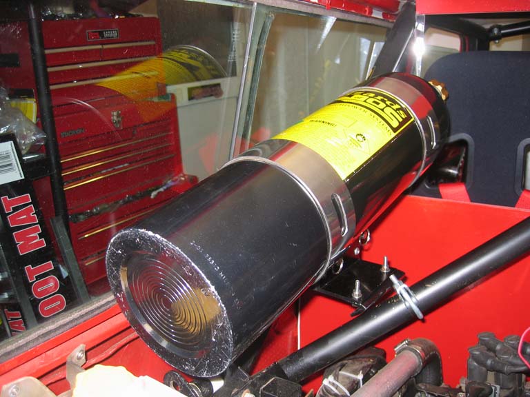
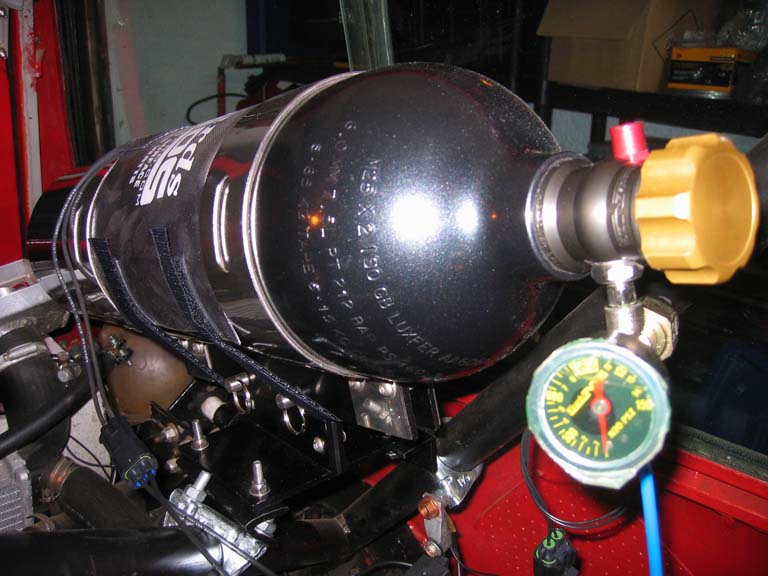
As we have such hot weather in the UK (NOT lol) I've added a bottle heater to the setup in order to maintain a consistent NOS pressure which avoids fuelling problems due to pressure fluctuations. This heater automatically switches off at a bottle pressure of 950psi. I also added a pressure gauge in order to check the pressure in case of heat buildup in the rear engine compartment causing it to be too high which could damage the engine from a lean condition being created from too much NOS and not enough extra fuel.
Fully installed at last, had a quick test and not that much noticeable difference (could feel it just not a big kick in the pants like you see in the movies lol) at the moment but that's with only 25hp on top of an already 340bhp so really a small hit in those terms.
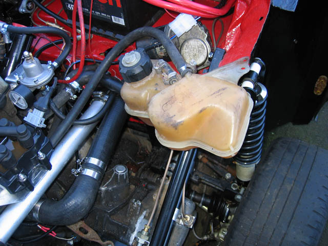
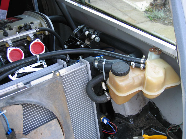
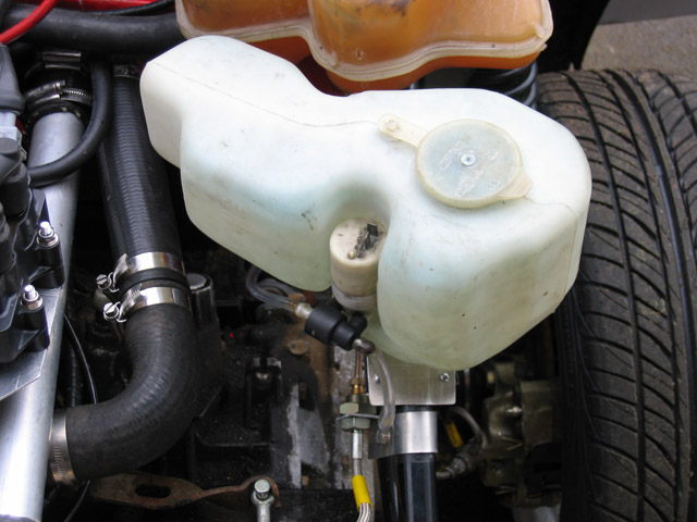
I found a good spot for the windscreen washer bottle just in front of the expansion tank, this is also a bottle from a Vauxhall so holds more water than the mini one and also appears to have quite a lot more flow and pressure from the built in pump.
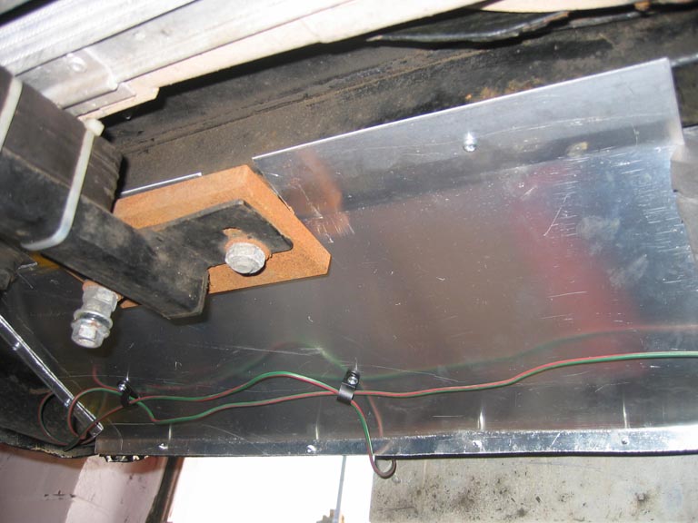
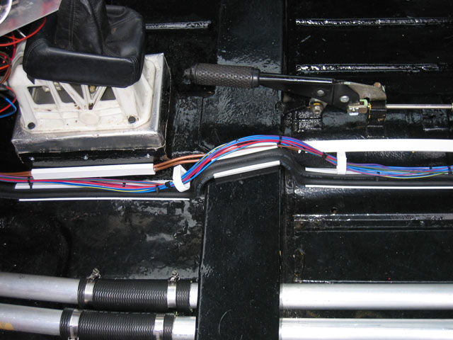
For the MOT (as well as looking decent) I have clamped down all the fuel lines, Brake\Clutch lines and the wiring to the rear of the car. Found that the electrical conduit from DIY stores was perfect for the job. I have now relocated the fuel lines beneath the car and used copper tube as the petrol smell in the car all the time was not particularly good.
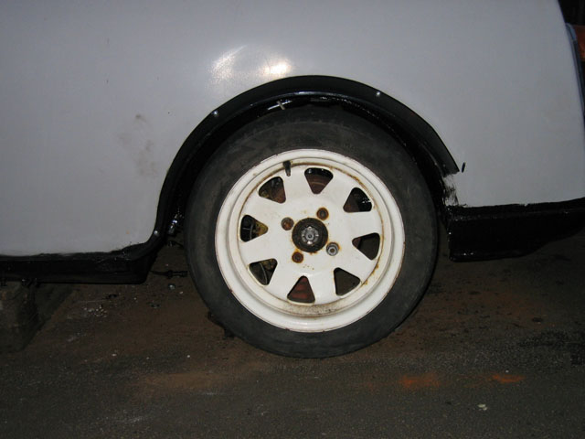
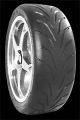
After the appalling grip problems experienced on the drag strip and the street I decided that some grippier rubber was required. After searching about I decided to try out the Toyo 888R's in a slightly wider 185 series than the normal Falken tyres which were 175. As the profile had remained the same at 60 the overall diameter has increased very slightly so should help with speeds available in the gears. The other benefit of these tyres is that they are V rated where all the other 13" ones were only H rated so capable of a sustained 150mph where the H are only 130mph.
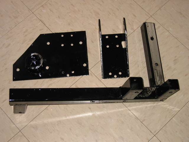
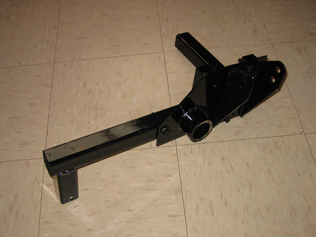
As the car had little or no good storage space attending a weekend show with camping gear etc would prove quite difficult. I didn't want to trailer the car to all the shows as the whole point of the car was to be able to use it as a proper road car and cars that are taken on a trailer to and from events I think are not really road cars anymore. To address this storage shortcoming I have installed a towbar as I already had a small trailer which could be used to store tools and camping gear etc for shows. I didn't want it to be a permanently visible bar so opted for a removable neck one and the install is quite hidden away when the neck is removed.
As I now had a slightly larger garage thought it was about time the mini got a facelift :o) Nice tango orange undercoat.
Finally in it's actual logbook colour.
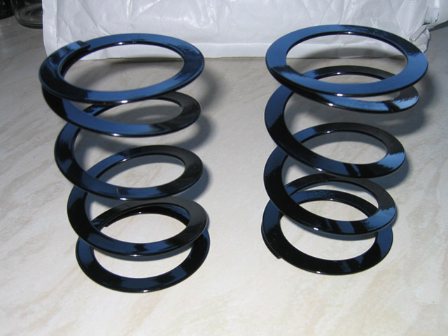
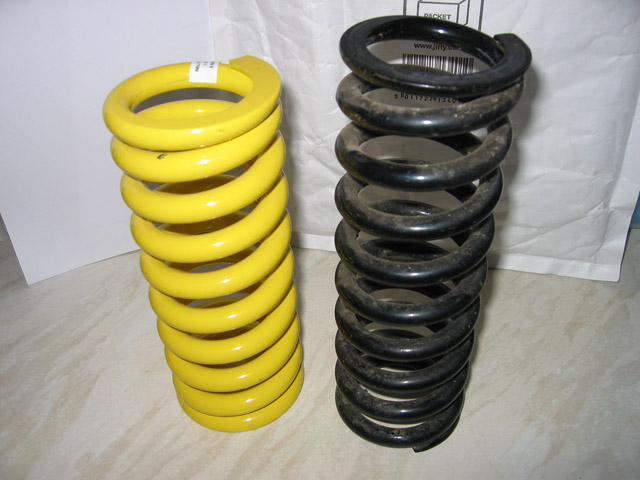
A fair while on and i'm having problems with the suspension being too soft which has 2 effects, the first being that the tyres can crash into the wheel arches and second that the large suspension travel when accelerating\braking causes a larger bump steer effect. To counter this i've ordered some much stronger springs which are 500lb instead of 275lb which is the stock mini AVO spring. Once this is done I expect that the car will sit too high at the front so the spring will need adjusting to compensate, this would be a problem as then when the suspension droops the spring will be loose from the top seat and that is an MOT failure and could also be quite dangerous. To fix this I have ordered some spring helpers that take up the slack from suspension droop but are that soft that they have no actual effect on the suspension otherwise. These are the spring helpers One of the new springs (yellow) alongside one of the old ones
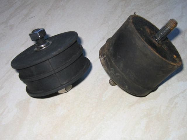
Another problem which was happening involved being unable to get gears on the rear engine at racing events, it would work fine on the road then play up at an event. After much annoyance constantly adjusting the linkages it was found that the root problem appears to have been the front engine moving around under load which upset the position of the gearstick link to the rear gearbox. I have tried to counteract this by fitting what seem to be much stronger engine mounts than the stock AMT ones supplied. These new mounts are from Series 2 V8 Landrovers, they are slightly larger diameter (only a few mm) and much less thick (38mm compared to 50mm). Having less thickness improves their stability as there is less rubber thickness to allow flexing however this then required some 12mm spacers to bring them up to the correct thickness so the engine would sit in the correct position, the rubber itself also feels to be a harder compound. Here are the mounts side by side with the new ones on the left. The engine can hardly be seen to move now when driving with the bonnet off and the in car vibration\noise hasn't noticeably changed.
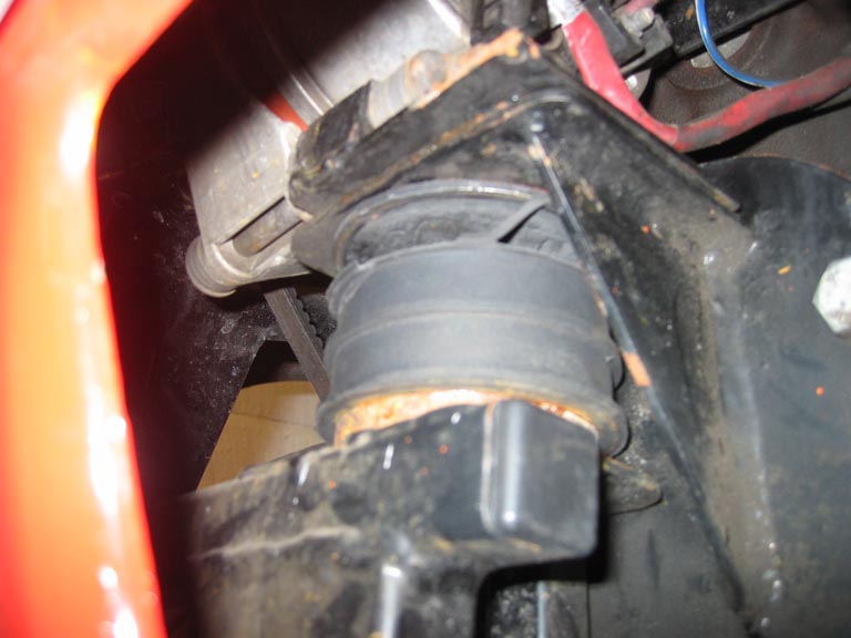
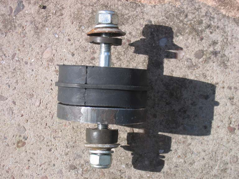
The new engine mounts were not strong enough on the front right of the engine and ripped completely into 2 pieces. I've now made a new mount from scratch using the middle of the ripped mount along with a cut up mini thrust arm bush which has a bolt all the way through, I think the bracket will break before this new mount and hopefully it won't make the vibration transmitted into the shell too bad with the bushes top and bottom of the mount.
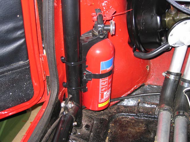
As was planning on some track sessions and maybe top speed runs now I thought it may be a good idea to add a fire extinguisher for emergencies.
Although I now had full heating in the car one thing that is a major problem on wet days is the windscreen steaming up, until now the only solution was RainX AntiFog and a cloth to hand in case of steaming up but now i've just fitted a heated windscreen to do the job. It's of the modern type with very fine elements in that are barely noticeable.
The front speakers were a little lacking in the volume department and I had some spare 6x9's lying around so I fitted these in the back, not much space left but they just fitted in there behind the seat under the roll cage door bar joint. It's much easier to hear now when travelling about and i've been able to reduce the crossover settings for the front speakers so these cope better now too with less bass.
|
|