| Build History Phase 2 | ||||||||||||||||||||||||||||||||||||||||||||||||||||
|
F20 Manual and 4T40E General Information F20 \ 4T40E Comparison
Engine Changes required to attach the 4T40 Transmission Block Changes Flywheel Changes
Electronics Required to Drive the Transmission 4T40E Electronic Control Module
Driveshafts Mechanical Selectors
Rear Frame\Suspension Modification Frame Changes Summary Suspension Changes
Front Frame\Suspension Modification Frame Changes Summary Suspension Changes Steering Rack Changes
Further Performance Enhancements Progressive Nitrous Controller Initial Test Traction Control Modified to use speed inputs rather than RPM
Replacement rear track rod ends More Handbrake Enhancement Wider Wheel Arches \ New Wheels Rear Transmission Cooler |
I decided to start a new build history section for 2 reasons, 1 being that the original build history was getting so large and 2 that the change to automatic gearboxes would be quite large and could get confusing with both the manual install and the automatic install in one area. (Click on pictures to see larger version) F20 Manual and 4T40E Automatic Transmission General Information The F20 gearbox is much smaller than the 4T40E Auto Transmission, the 4T40E Transmission itself was about the smallest Auto box I could find that would even have a remote chance of fitting into the mini and also be strong enough to take the current and future power from the engines. The F20 would be at it's reliable limit at around 200hp where the stock 4T40E can take 250bhp easily. There are numerous upgrades available for the 4T40E transmission that enable it to take 600hp+. Another benefit of the auto box is the gear ratios are much more suited to the mini's small diameter wheels, here is some comparison info of the F20 and 4T40E in gear speeds.
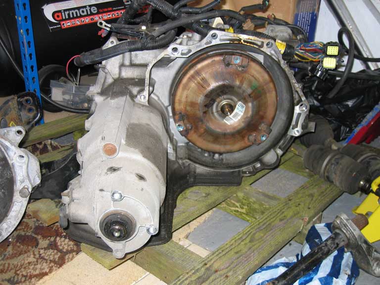
The reason the 4T40E would be an option was that the problem with most auto transmissions is the width of the box from the engine block which would totally make the install impossible due to the narrow nature of the mini whereas the 4T40E box has the gears behind the engine with just the primary torque converter and drop gears etc at the side of the block making this transmission actually narrower than the F20. The rear mounted gears wouldn't be such an issue at the rear but at the front I expect some bulkhead modification may be needed along with moving the steering rack somewhat. Another issue would be controlling the automatic transmissions as they use virtually all electronic control so would require ECUs and wiring where the F20 was simply mechanical. F20 4T40E
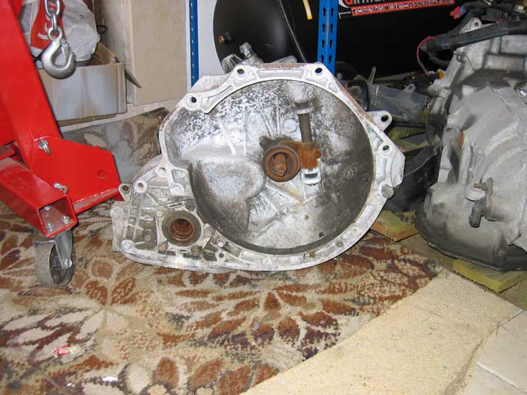
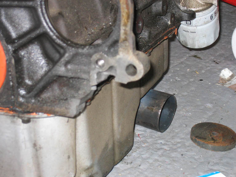
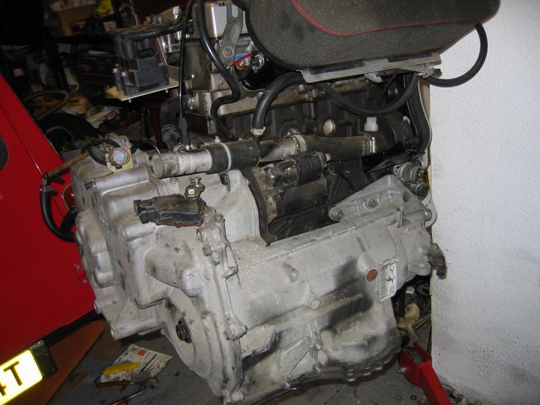
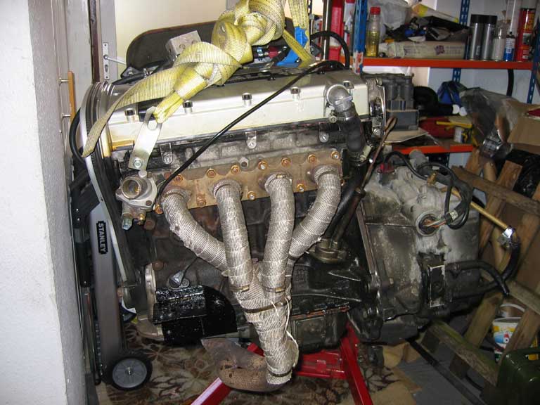
Engine Changes required to attach 4T40 transmission The C20XE never came with an automatic option so in order to connect this transmission to the engine I have needed to cut a small amount of block away near the starter motor in order to clear the rear section of the transmission and also will require a flexplate from a V6 C25XE or X25XE engine to connect the crank to the torque converter.
The flexplate was a bit of a nightmare, 1 to find any as they usually get thrown away and 2 to make it fit. The V6 flexplate will only fit correctly with the spacer included and then the bolt holes for the torque converter didn't line up so I had to drill these myself, luckily the accuracy of these bolt holes isn't very critical as they don't perform any centering of the torque converter as this is done by the shaft that fits inside the crank.
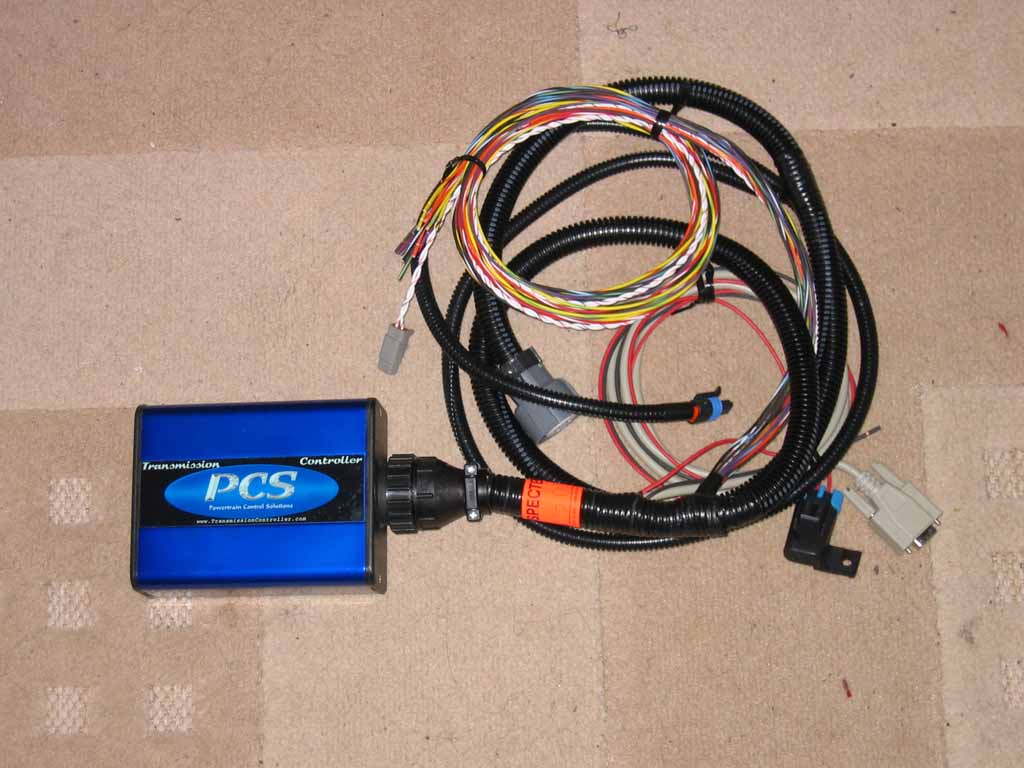
Electronics Required to Drive the Auto Transmissions Along with the frame modification requirements the other biggest problem will be controlling the auto transmission as these models are fully electronic controlled, there are a couple of control units available in the US which I will be investigating and will add the info as I find it. After a large amount of checking into options for the transmission control I am going to go with the TCM-2000 controller from PCS. This was the 2nd most expensive controller I found but it has by far the best features that are fully configurable for road, track and drag modes.
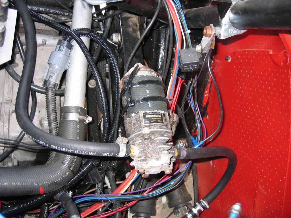
For the rear auto transmission I wanted to be able to run as before with only the front engine in use. Although the 4T40E transmissions support tow mode this is limited in range and also speeds that can be used (100miles and more importantly 40mph due to the small mini wheels). To counteract this limitation I needed to install an electronic pumping system that would circulate the transmission oil to the bearings for cooling\lubrication while the engine was off. There was a system available in the US for this very job but at a cost of £500+vat and shipping was expensive. A cheap similar version has now been installed using a pump from a Nissan S14 200sx and 2 one way valves to ensure the fluid flows the correct way around the transmission while being electronically pumped or mechanically pumped.
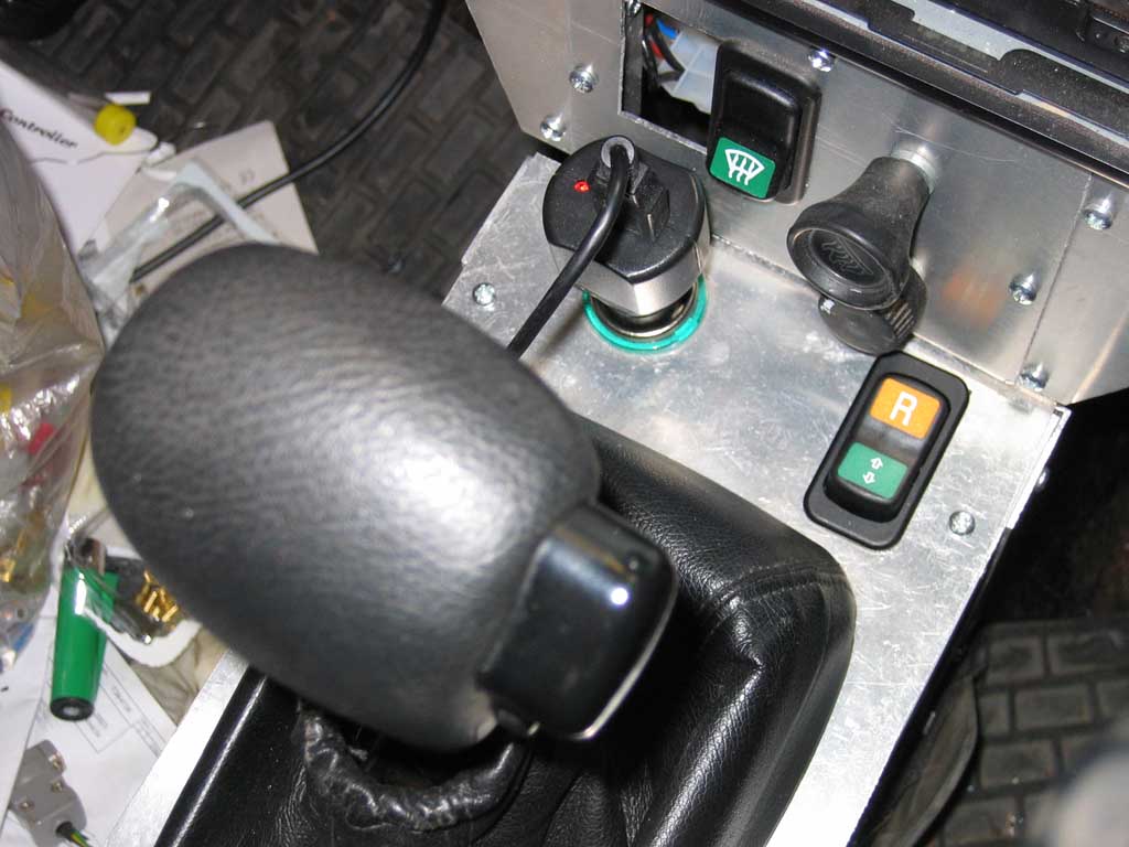
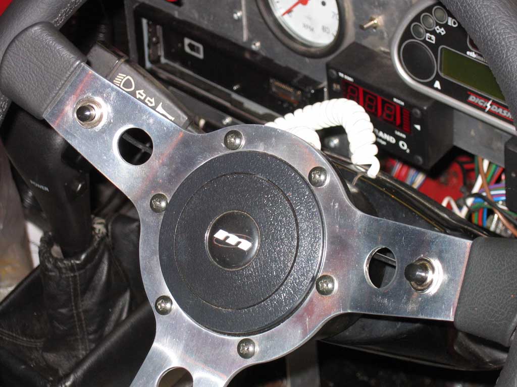
The PCS controller has many modes that are selectable including 2 completely separate base maps which can be selected electronically. This switch enables switching between Map A (Normal Driving) and Map B (Racing) also in the other position it enables sequential manual mode utilizing the two buttons mounted on the steering wheel to select up\down shifts manually for track use.
As the 4T40E Inner CV joints were a different spline pattern and also the shaft length needed to be shorter I will require new driveshafts, I have two options which are to chop\weld existing shafts to create new ones or to buy custom one piece shafts. While the making shafts out of two pieces may be cheaper overall I will be going with the new shaft route (mainly for the strength\reliability aspect). The shafts are somewhat shorter than the old AMT ones and also much closer to equal length than before with no dummy shaft required so I am hoping that torque steer will be reduced. Original AMT shafts :- 350mm and 250mm
New Shafts :- 215mm and 267mm
The new shafts are slightly thinner at the transmission end due to the 4T40E transmission compared to the F20 ones, I don't think this will be a major problem since the original shafts used on the 4T40E were 1mm thinner than these new ones, they used a lower grade steel and the original cars that use this box have been running 360hp+ V6 Turbo's.
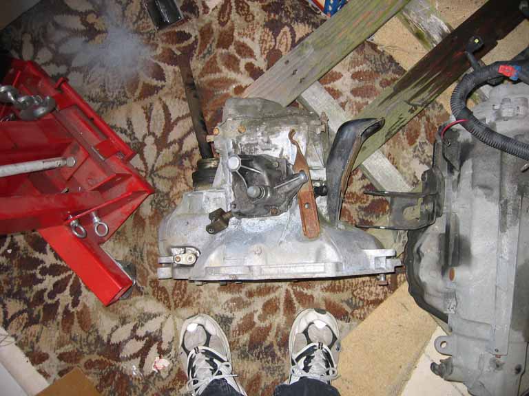
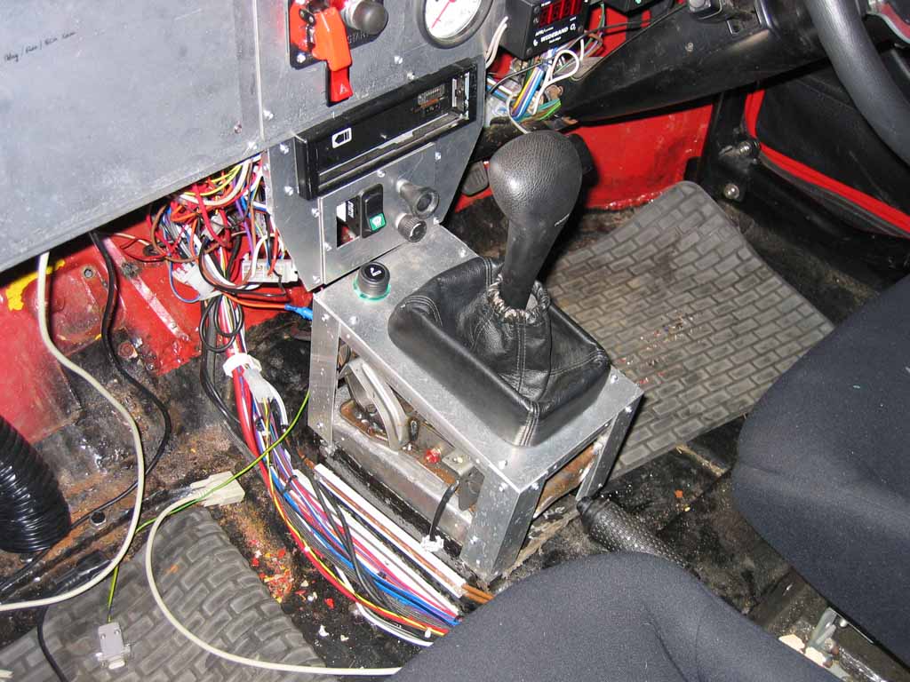
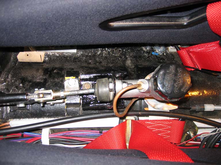
Although the transmission is virtually all electronic it still requires a manual selector to engage Park, Neutral, Reverse and Forward Gears (I think without any electronics at all it will run in limp mode as you appear to get Reverse, Neutral and 3rd Gear when I tested the engine earlier). To keep things simple for the front I have been able to use the stock selector box and the original cable from the donor car (it's a little on the long side but with a bit of bending around it just fits). Rather than try to incorporate the rear engine into this shifter I will create a new separate unit since there's no reason for a single shifter as with the manual boxes (no need to shift apart from selecting drive\reverse initially) and will make things more simple to install.
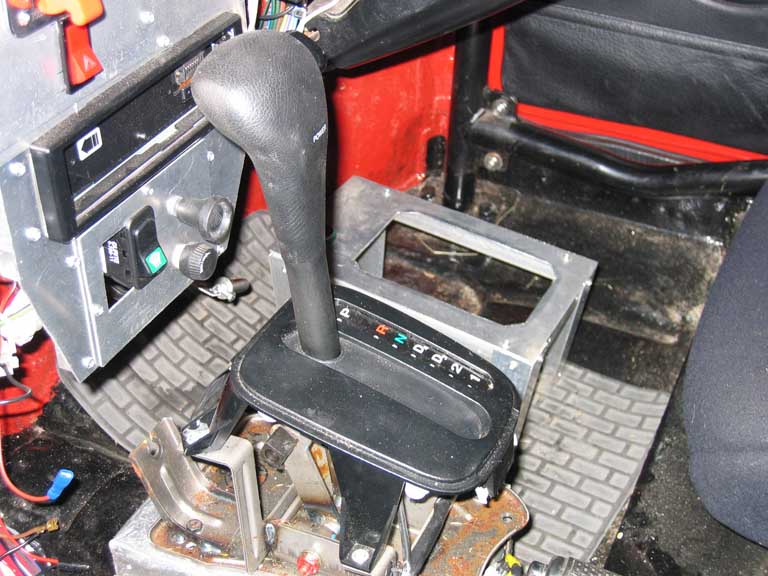
My existing dashboard wouldn't really fit around the stock selector so I removed the upper plastic part and installed my old gear surround and personally think is looks much better now although as a downside you can't see which gear is now selected.
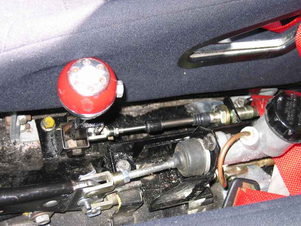
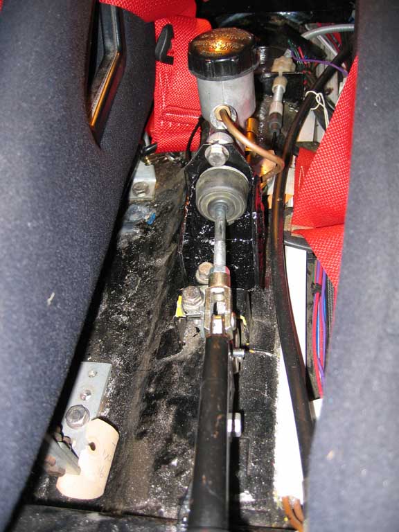
This is the gear selector for the rear transmission, as the auto boxes are simply placed into Drive or reverse etc there was no need to have a single unit that was connected for synchronous shifting. I will be adding some sequential paddles to the steering wheel in the future for track events etc and these will select gears on both transmissions at the same time.
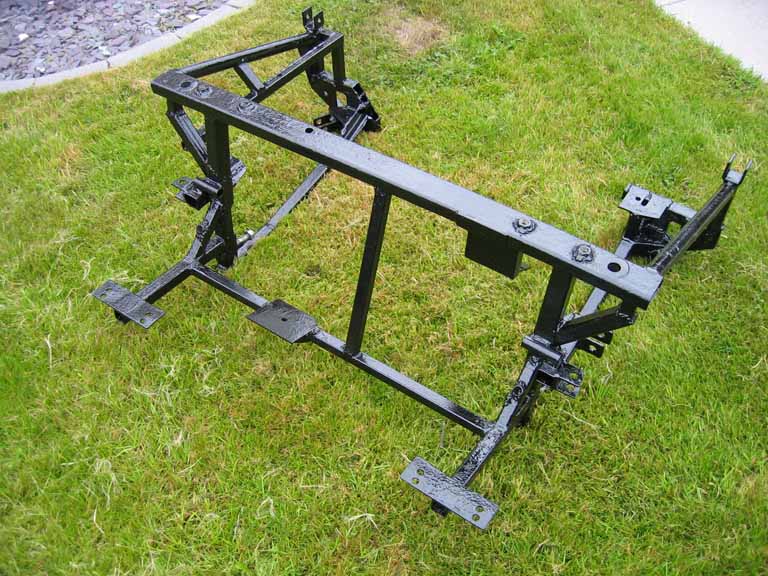
Rear Frame\Suspension Modification for Automatic Transmission Installation The AMT frame has needed extensive changes to install the transmission, many more changes that I had hoped were required. The main frame lower section has needed to be widened by approx 30mm each side which was difficult, a new side gearbox mount created in order to use the stock gearbox mount (this will prob be better than the universal mount used before) and a new set of rear mounts created. The driveshaft connections sit slightly further back than the F20 necessitating a small amount of cutting on the rear of the frame to clear the CV joints. It does now just fit in there tho :o) With the widening of the frame overall this would obviously also widen the track of the car by approx 30mm per side, I really didn't want a huge track needing huge wheel arches so I have managed to shorten the suspension arm length by 10mm and also removed the wheel spacers to get another 10mm however the wheels still protrude beyond the arches so will require some slightly larger arches.
There is another problem which has become apparent in that due to the shorter driveshafts the suspension cannot sit as high as it did before or the driveshafts foul on the outer part of the inner CV joints due to the angle of the driveshaft, in lowering the suspension enough to combat this driveshaft angle issue it looks that will have to return to stock mini size tyres (175/50x13) or have problems with the tyres rubbing the arches even more than before. However as noted above the gearing of the auto box negates the usual problems of too much rpm when cruising but means another expense for new tyres which I hadn't prepared for.
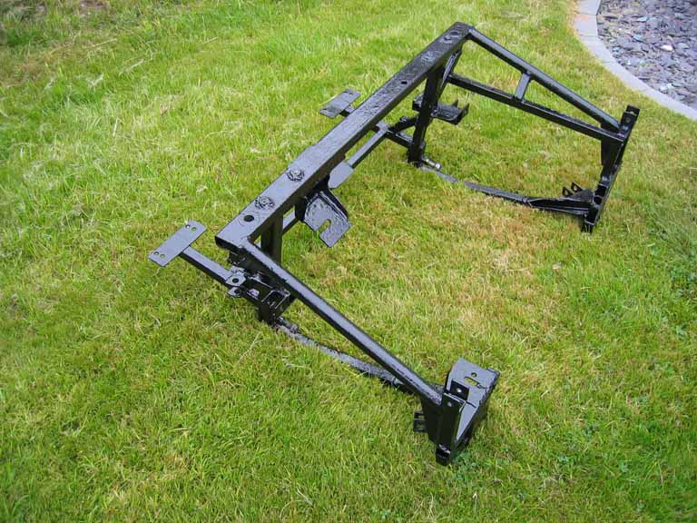
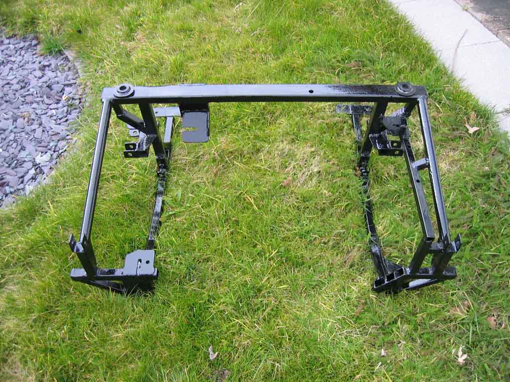
Front Frame\Suspension\Steering Modification for Automatic Transmission Installation The front frame required similar modification to the rear with the widening to clear the gearbox however the rear gearbox mount needed to be different as there wasn't space to match the same setup as was used on the rear. You can see that the rear mount sits right in the corner of the frame at the back and I think that this position may actually be stronger than the design of the mount for the rear frame.
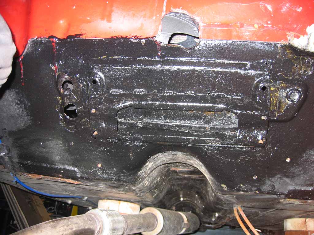
Similar changes were made to the suspension in line with the changes to the rear. The biggest issue at the front was the steering rack as this was fouling on the back of the gearbox, in order to get around this problem I had no choice but to move the steering rack approx 1.5" downwards. Due to the angle of the panel where the rack is mounted this has resulted in lowering the rack approx 0.75" and it now sits approx 0.75" back. To try and combat any possible issues with steering arm angles etc I am going to use the slightly longer metro arms which also sit lower. Normally if widening the suspension pivot points the rack would need to be widened in order to maintain the same relative position between the upper and lower arms, with moving the rack down this has returned the pivot points to near centre between the upper and lower arms.
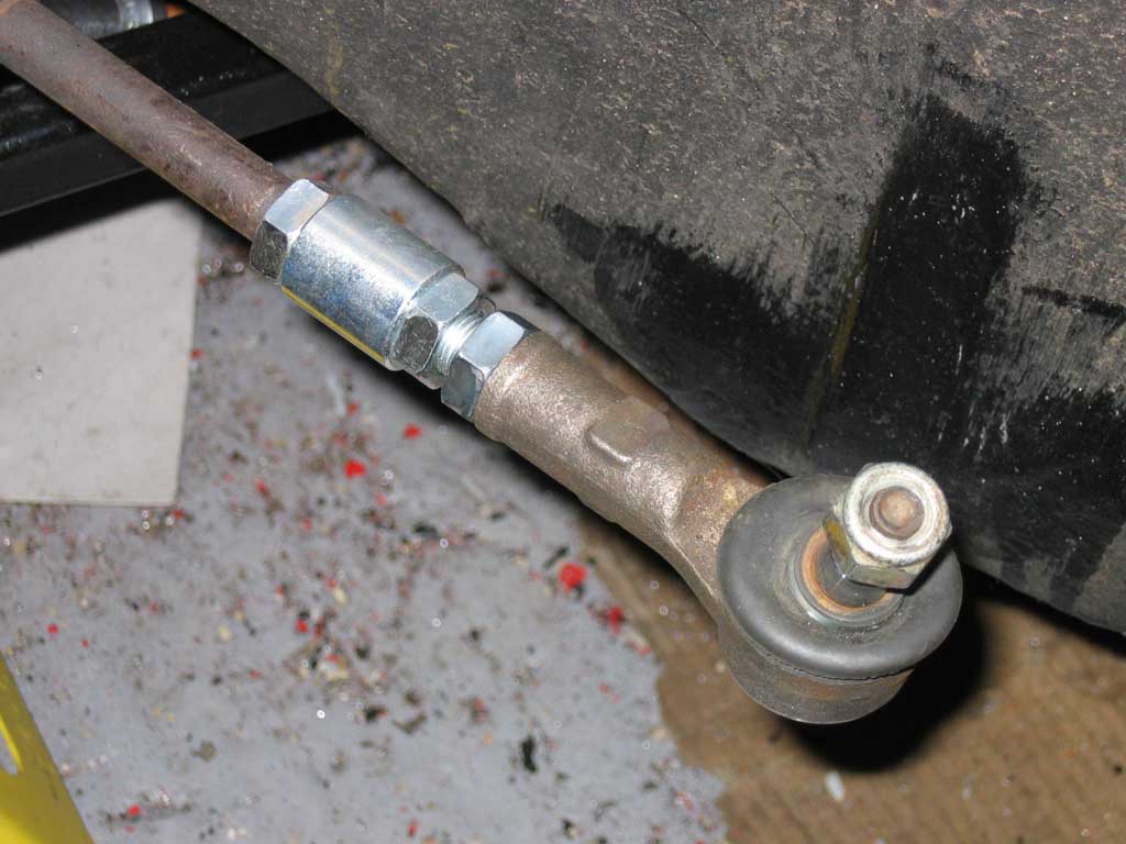
Due to the widening of the frame the steering rack arms are no longer long enough to track the front wheels properly, I tried the spitfire track rod ends which are longer than the stock mini ones but they were only 1 thread on to get the wheels near straight so another option was required. I looked into maybe getting a rack from an Austin 1100\1300 as these are wider but use the same fitment and steering column fitting but have a much lower ratio meaning more turns lock to lock, where this would be good for holding on to it with torque steer it needs to be decent for track sessions and loosing that much steering ration would make it harder for track days. In order to retain the stock rack part of the track rod arms were cut off, a decent thickness tube was added so that approx 1/2" of thread was used of the existing track rod and another 1/2" of thread was available to connect an extension bar. This was very tight as by adding the joint section the track rod ends are just able to be screwed in far enough to create a little toe out (just needed some room for adjustment as when the car is properly aligned it could require a little adjustment compared to how it has been set by me) but can easily be adjusted now for straight\toe in.
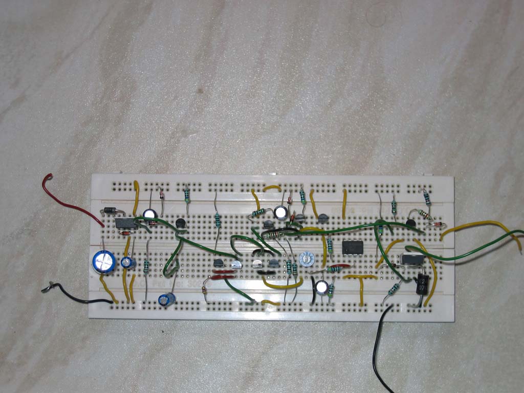
Further Performance Enhancements Now that the performance is consistent I can begin to increase the available power until the limit of the transmissions or the limit of grip is reached with the current setup. As there is already a fixed nitrous shot of 50hp on the rear this can't really be increased without risk increasing on the engine and transmission due to the sudden torque increase. To improve on this situation and run 100hp+ of nitrous there needs to be a progressive controller available to steadily increase the nitrous supply over a set period to limit the shock to the engine and transmission. Rather than purchase a ready made progressive solution I decided to go down the DIY route which may not be as elegant or professional as an off the shelf unit but much more rewarding (if it works), more compact (I intend to integrate front and rear controllers into one unit) and a lot less cost. I located a pre-tested circuit diagram which has been successfully used by several people to control nitrous and set about constructing the prototype.
This single unit is functioning correctly on the bench and has variable pulse frequency (10-100hz), start % (approx 10-40%), build time (0.1-10 seconds) and max power (50-100%). Since moving to the automatic transmissions I have decided that turbo power would make sense since there is no need to lift off the throttle between gears it will ensure no loss of boost pressure between gears. The nitrous install will still come into play eventually but for the moment is on hold.
The front transmission shift from 1st to 2nd gear is resulting in traction loss due to the excess torque being dumped from the engine at max rpm into 2nd gear. The current traction control setup was using engine RPM for traction monitoring, while fine for the manual setup this isn't really ideal for the automatic transmission setup as there can be slight variances in RPM at the same speed due to transmission slip, torque convertor tolerances etc. As a result of this problem I will switch the traction control inputs to use the transmission control unit speed outputs. Hopefully as these are fully configurable pulse frequencies I will simply be able to rewire from the old RPM signals to the speed outputs on the TCU's and everything will behave as before. Another benefit of this setup is that in the future as the engine power is increased I want to use different shift points for each engine so the RPM would totally be unsuitable in that situation. I completed this work and it's performing perfectly stopping all wheelspin within moments of breaking traction, required a lot more changes than planned to make it work properly due to the larger frequency range required for speed and also some signal damping to stop small spikes causing the traction control to kick in.
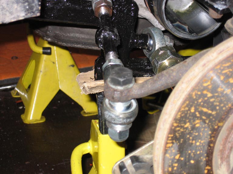
General Changes \ Improvements While completing this many changes to the Mini it was a good time for a full tidy up of other areas such as suspension links etc. I was going to fit rose joint rubber boots but found that really there isn't enough space for these on most of the joints so changed my mind and left them off. There was a small amount of play in the rear steering arms and it was caused a little by the track rod ends, to help combat this problem I have replaced the track rod ends with rose joints, this simply required drilling out the hole in the steering arm on the hub to 1/2".
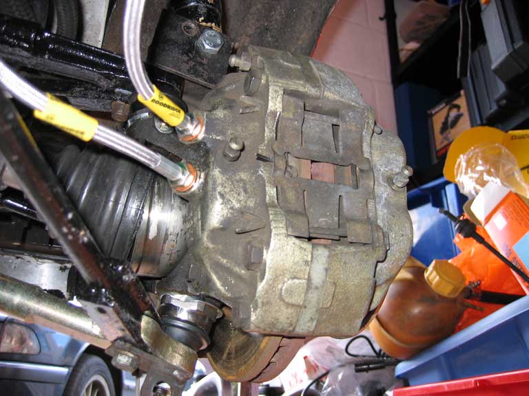
The handbrake setup is still far from efficient so to improve this situation further and also lower the main rear brake efficiency (even with the balance bar set max effort to the front the rear still locks up before the front sometimes currently) I have split the 4 pot rear calipers into separate halves so that the upper pair of pistons will be used for a hydraulic handbrake assist and the lower pair of pistons will work the primary braking effort. The mechanical handbrake setup has to remain in place however as it's a legal requirement for the handbrake to have a mechanical function but the hydraulic part can assist.
This setup feels much stronger than the mechanical one as with only minor application of the handbrake lever you can't push the car whatsoever and that's without the mechanical part currently connected. :o)
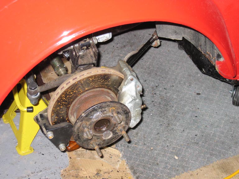
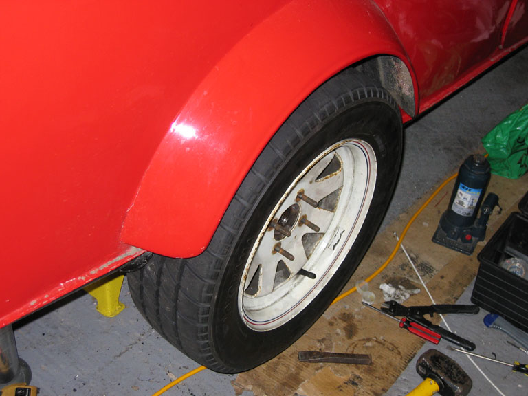
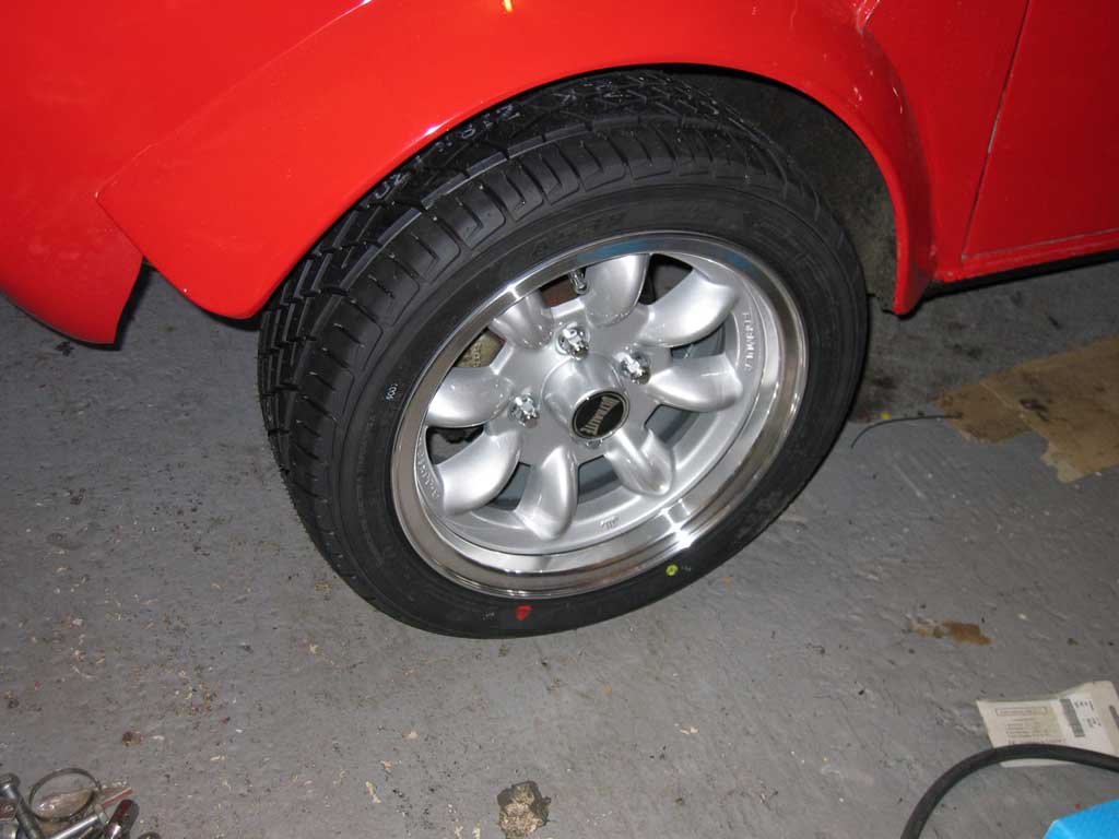
Rather than just replace the tyres with the stock mini size tyre I felt time for a change so opted to get a complete wheel\tyre package so got a set of 6x13 Ultralites with Yokohama A539 tyres.
As you can see from the above picture the wheels stick out beyond the arches so wider arches were required, I already had a set of Watsons arches which weren't used during the initial build but they were perfect for this job as they are about 3/4" wider than my current ones. Still need to be painted etc but they are much stronger than the old ones.
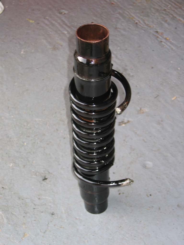
The automatic transmissions require cooling as opposed to manual transmissions that rarely require a cooler, the front one was simple as I already had a suitable radiator with the automatic connections available but at the rear the large radiator i'm using doesn't have this option. Rather than begin searching for yet another radiator and another large spend (auto radiators are much more expensive than a non-auto radiator) I have fabricated a cooler that will install into the lower main water pipe. This is constructed from a copper primary tube and then wrapped tightly with 10mm microbore copper tube which is then soldered to the primary pipe for maximum heat exchange.
This heat exchanger will hopefully act in 2 ways, 1 to cool the rear transmission on long journeys\racing and 2 to pre heat the rear engine somewhat while travelling to a racing event saving on the warmup time for the rear engine before racing.
The old fan cover didn't fit the new lighter fan assembly so I made a new one out of aluminum this time.
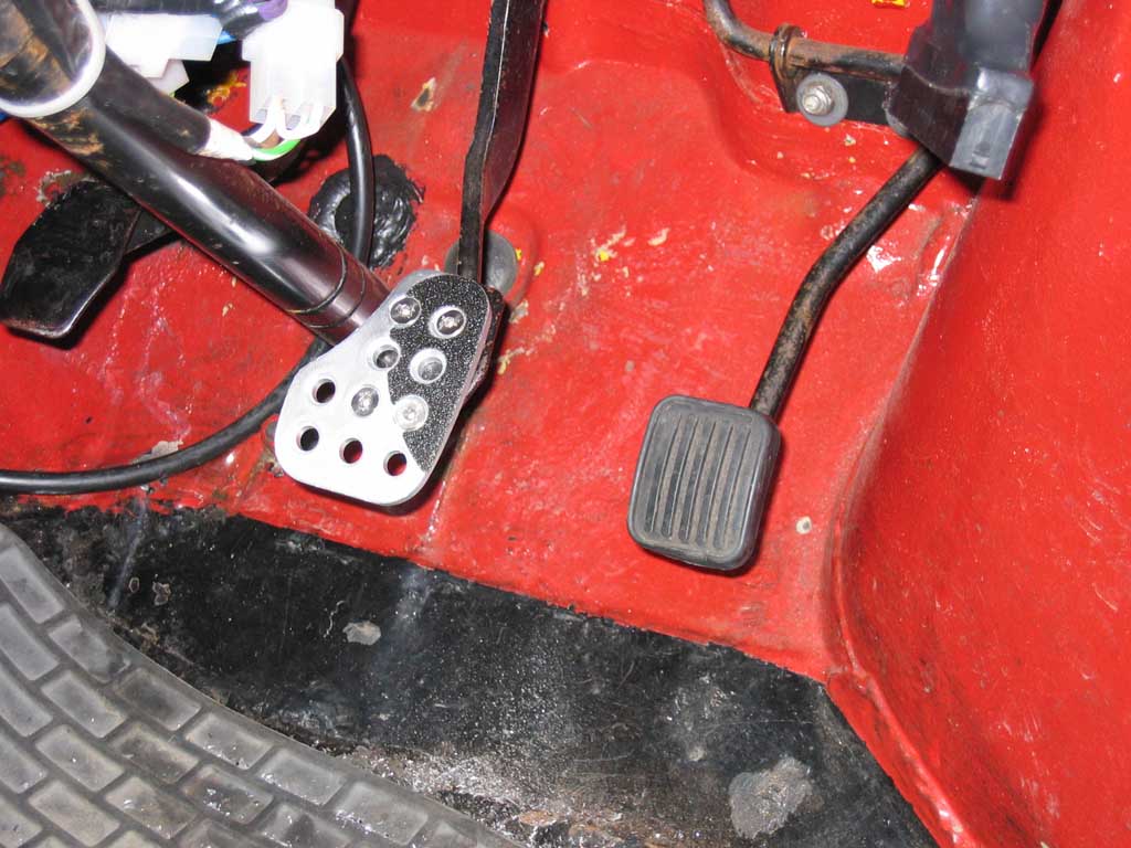
With the steering rack lowered the small stock mini brake pedal was quite close to the column which wasn't comfortable to use as your foot didn't sit well on the pedal. To improve the situation i've fitted a larger brake pedal from OMP and it now feels much more natural.
|
|||||||||||||||||||||||||||||||||||||||||||||||||||