| Build History Phase 5 | ||||||||||||||||||||||||||||||||||||||||||||||||||||
|
Automatic Transmission Rebuild Strengthened Internals Change Final Drive Limited Slip Differential Electronic Boost Control Upgrade Internals Further Side Window Rear Engine Radiator Air Intake\Exhaust
|
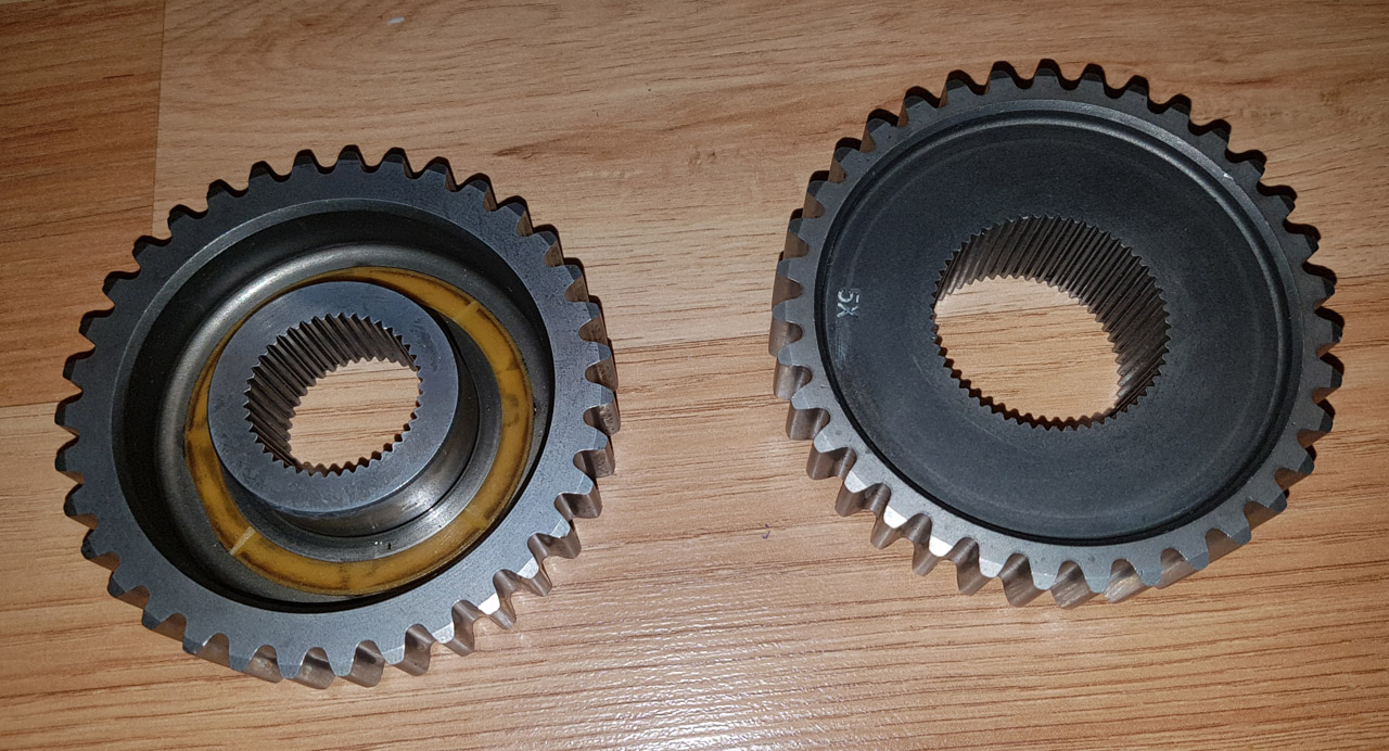
This section will detail some power and speed enhancements. (Click on pictures to see larger version) While the overall gearing of the automatic transmissions is an improvement over the manual F20's 1st gear is still a bit short to be of any real use with any sizable increases in power. To combat this I will be changing the drive chain sprockets in the transmissions from 32\38 teeth to 35\35 teeth from a different variant used in the US on the larger engine capacity vehicle, this will change the final drive from 3.91:1 to 3.26:1. This will also aid in top gear cruising ratio's, the table below shows the outcome of the change.
Hmmmmm, that would make an interesting top speed now of 178mph at 6500rpm which would be which may actually be achieveable with over 700hp despite the poor aero of the mini. :) (6500rpm is conservative on the engines, should be able to do 7500rpm fairly easily on the setup which would be 205mph or even 215mph on the 225's but can't see that somehow lol)
These are the 35T sprockets that will be used during the rebuild to change the FD ratio. Will add a picture of the originals for comparison once removed.
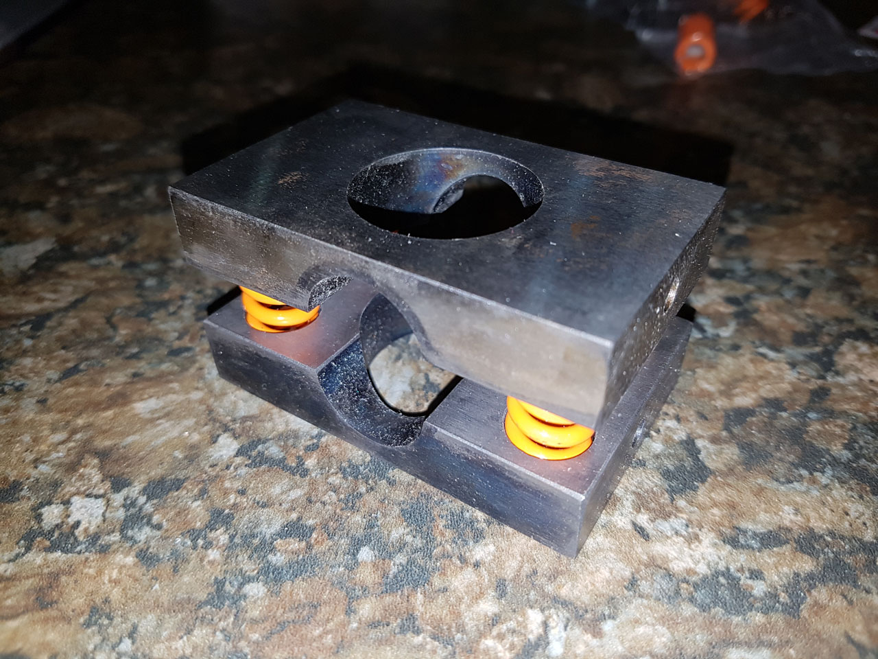
The options for this item are extremely limited for these automatics, the majority are simple sprung plates which work against the spider gears in the open differential to emulate a plate LSD function but relies on friction between the spider gears and the casing. The other option is similar but a modified solution which fits small clutches between the spider gears and the casing which is a little more enhance that the basic sprung plate design but the same pricipal. There is quite a significant price difference between the options so still investigating which to go with on a low mileage use car. Based on my research into these options I will be going for the Team Green LSD, while this is the more basic option it appears to be fine for the purpose required. If the car was a daily use vehicle expected to see high mileage then the more expensive clutch converted item would have made more sense. Will add more pics when installed.
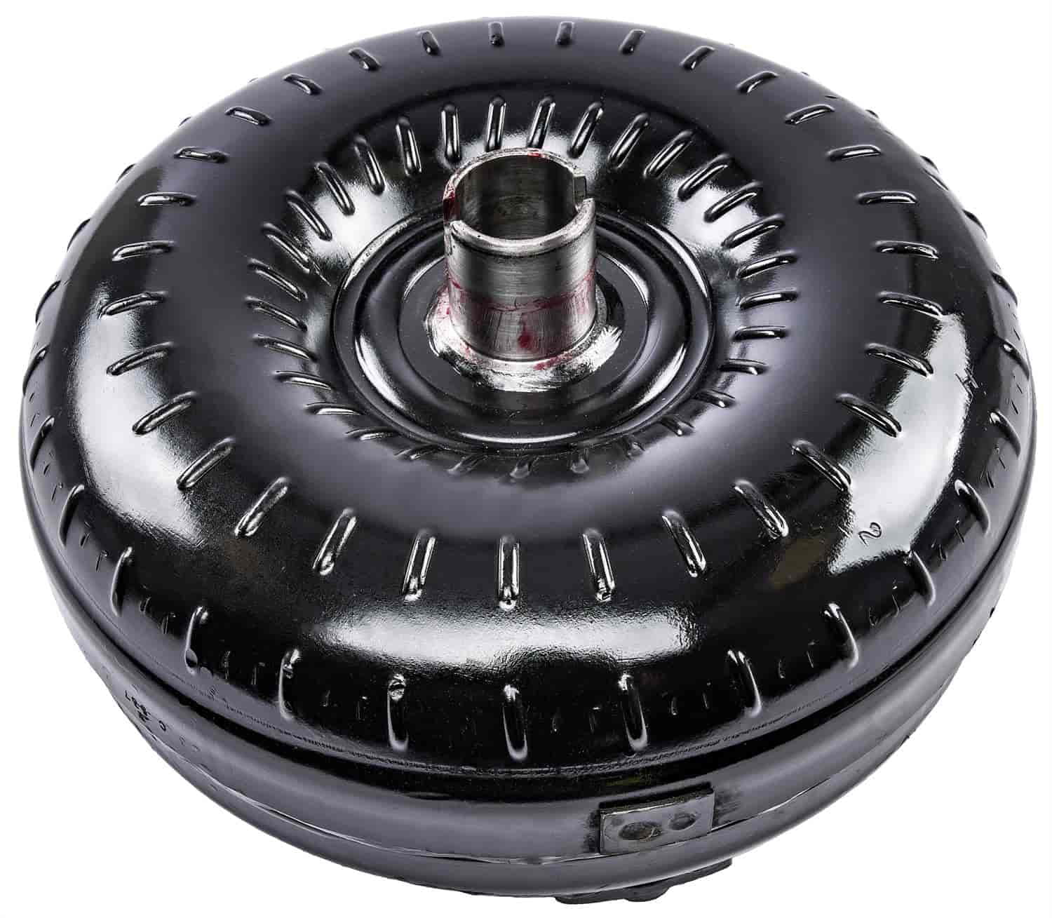
Strengthened Internals in the Transmission The physical side of the transmission is already fairly robust and should cope with the amount of power that will be thrown at it in a car of this weight, the weaknesses are primarily in the clutch friction material and the torque converter. This is a GM42CW torque converter which will now be used on the rebuilt units, the stall speed is slightly lower at around 2000rpm compared to 2350rpm of the original (the lower stall is suitable as the torque has increased massively compared to the normally aspirated engine). The new converters are also woven carbon compared to paper of the original units so are able to take more load without failure.
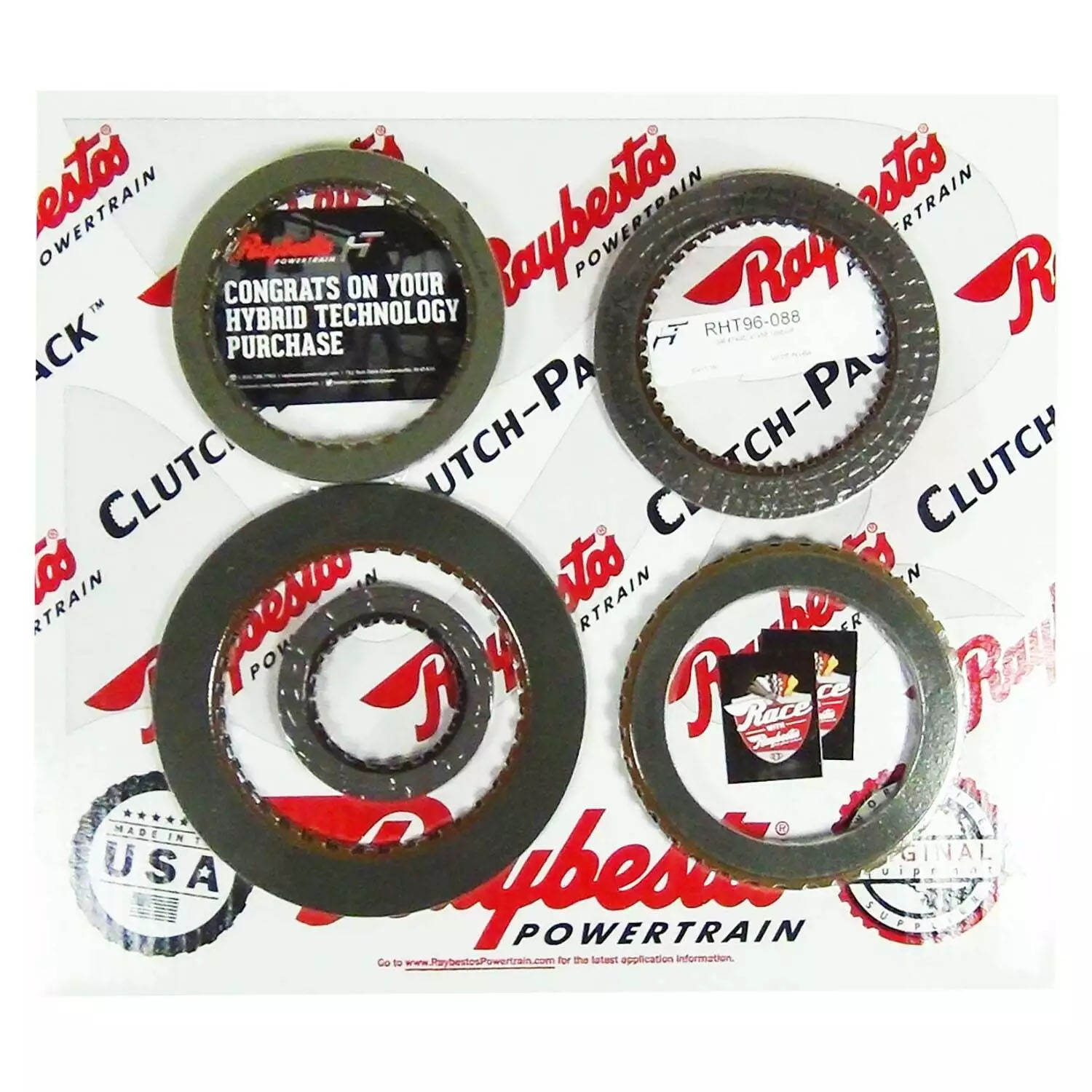
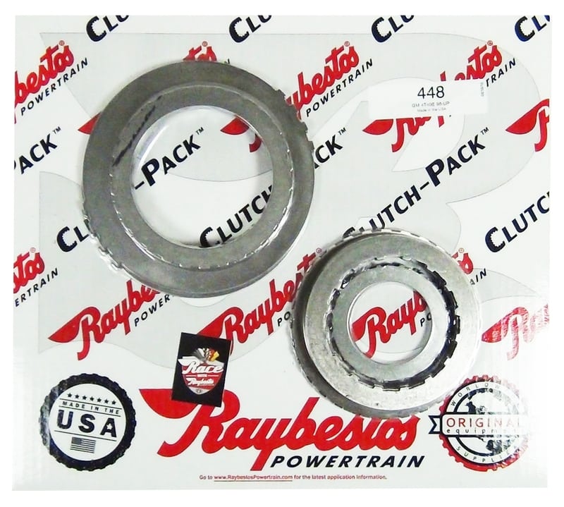
Raybestos Friction Clutches and Steel plates are also being installed which are able to take additional torque above the stock plates, with these upgrades the transmission should now be able to handle up to 400lb/ft of torque which is beyond what I will be producing even with the rebuilt engines.
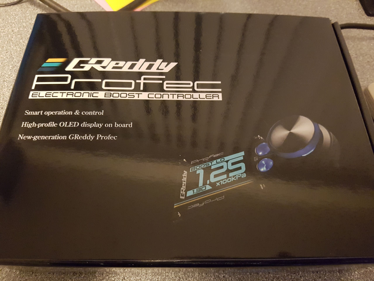
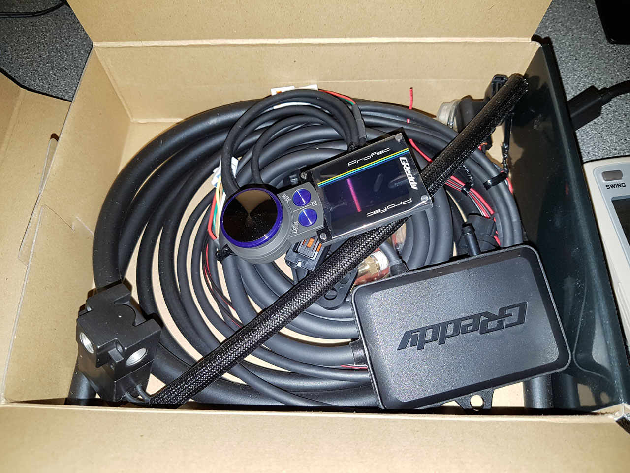
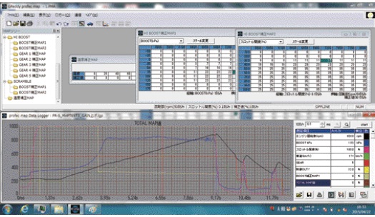
Once the engines are rebuilt I will be wanting to run likely around 1.5bar of turbo pressure for the planned 300-350hp output. In order to do this in a controlled manner I have opted to purchase a couple of digital boost controllers, in this case the newer Greddy Profec. I used to have an Apexi AVC-R in the Skyline which was brilliant but the greddy is so compact it was much more suitable with little dashboard space remaining available for yet more gadgets. These will then allow me 3 different boost setting off (actuator pressure) low and high along with a scramble boost setting should I want to add a timed overboost option. This unit also has the capability to perform as per the Apexi with variable boost against rpm with an additional module added but for now the default will suffice.
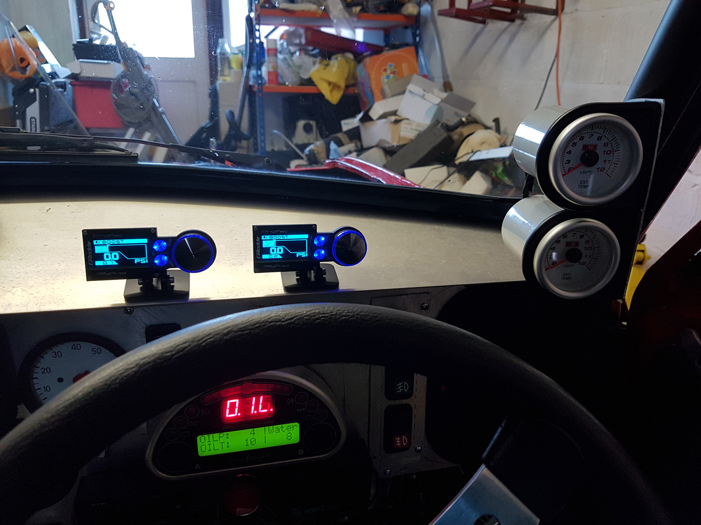
All installed ready to go, have removed the old mechanical boost gauges too which looks much tidier and they were blocking visibility a bit too when there were four mounted on the side.
This is a quick video of the startup sequence, if it keeps getting more gadgets it will soon rival Knight Rider lol I have also now purchased the map module upgrade for the boost controllers, this will allow RPM and TPS based boost mapping similar to an ignition\fuel map. This may enable more boost to be run at higher rpm ranges where the higher compression currently won't cause pre-ignition but such a boost level at a low\mid RPM could cause this issue.
The engines were already strengthened in the original build so this will primarily be a refresher build with the addition of new pistons to complete the setup by lowering the CR to around 8.8:1.
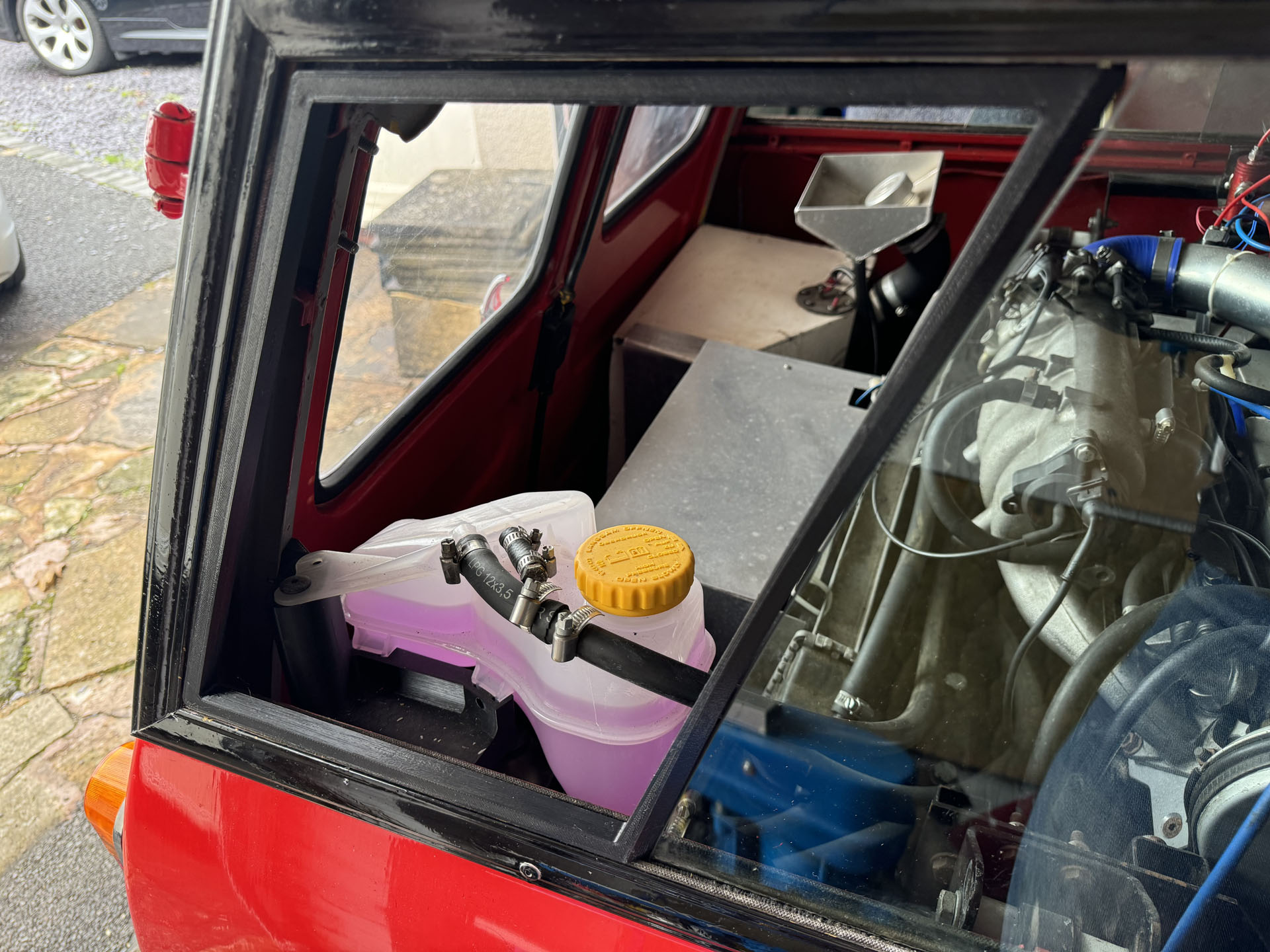
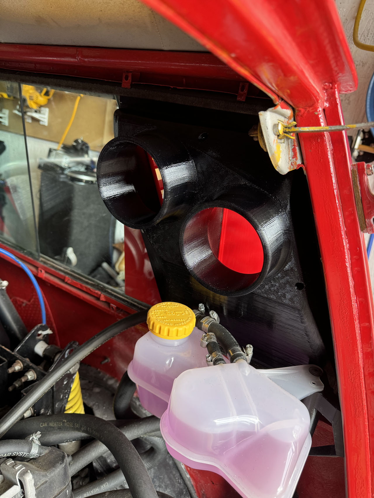
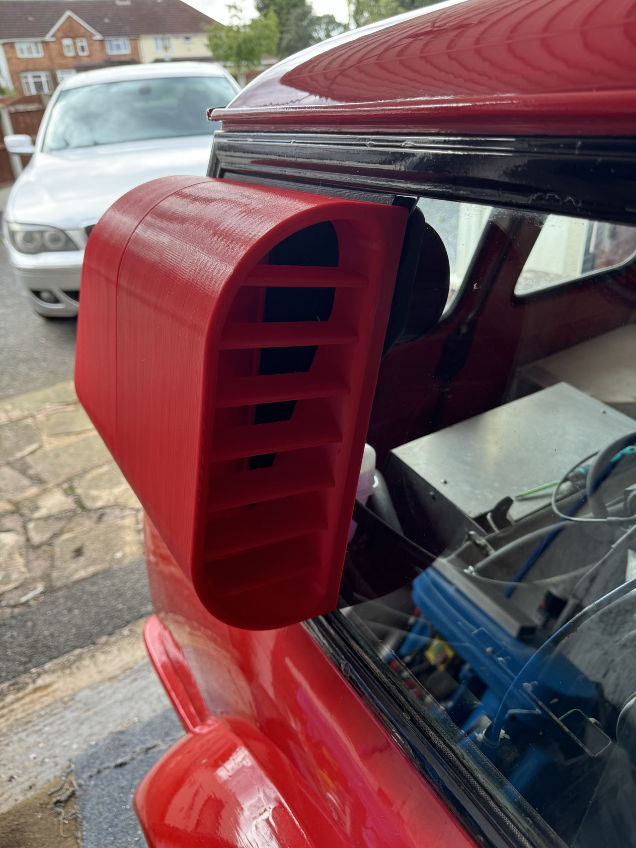
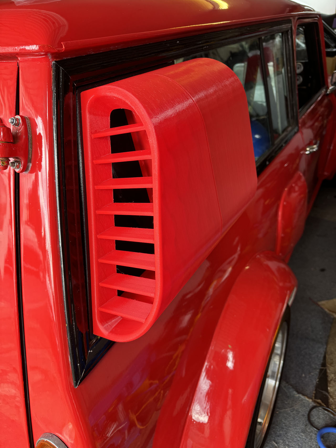
Cooling the engines (especially the rear) is on ongoing battle, the rear issue being airflow through the radiator and the front engine the size of the radiator. Whilst I already added an extra little radiator to the front when the engines are next out I will install 2 new radiators behind the new front bumper air intakes (most likely some motorbike ones as these can be purchased in a curved design which should fit better. Hopefully once these new cooling enhancements are in place I will be able to do a full track session not just shorter sprints and drag racing. Despite the rear radiator being pretty large it simply wasn't getting enough cold air through it even when the fan was running so I finally managed to force open the rear side windows and designed\printed a large air intake and also air exhaust rather than let the hot air circulate around the rear compartment (i'm hoping this should also help mean the drag isn't too large from the intakes as the same amount of air will be expelled at the rear). These are currently simply printed in red plastic, may paint them properly at some point but the red isn't a bad match as it is. On the inside of the assembly there are 2 outlets, 1 takes the cold air to the radiator and the other takes the hot air back out. They won't be piped in just you though until I do the engine rebuild as I intend to do a large amount of pipe rerouting and tidying as the same time along with repositioning the radiator.
|
|||||||||||||||||||||||||||||||||||||||||||||||||||